How to Write a PLC Program to Start and Stop a Motor
In this video, you’ll learn how to write a PLC program to start and stop an electric motor and test it using PLCSIM.
This is another article of the free Siemens PLC programming series.
We’re going to see how we can start and stop an electric motor by writing a Ladder logic PLC program using Siemens TIA Portal V15.1.
It may sound very easy! But let’s see which important practical points are hidden in this simple PLC program!
If you haven’t watched Part 1 of this series about “Creating a new Project and Configuring its Hardware in Siemens TIA Portal”, then take time and read that blog post before this.
How Many PLC Cards do We Need?
As always, first, we have to calculate the number of inputs and outputs of the process to and from the PLC cards.
We have two pushbuttons;
– One for starting,
– The other for stopping,
the electric motor.
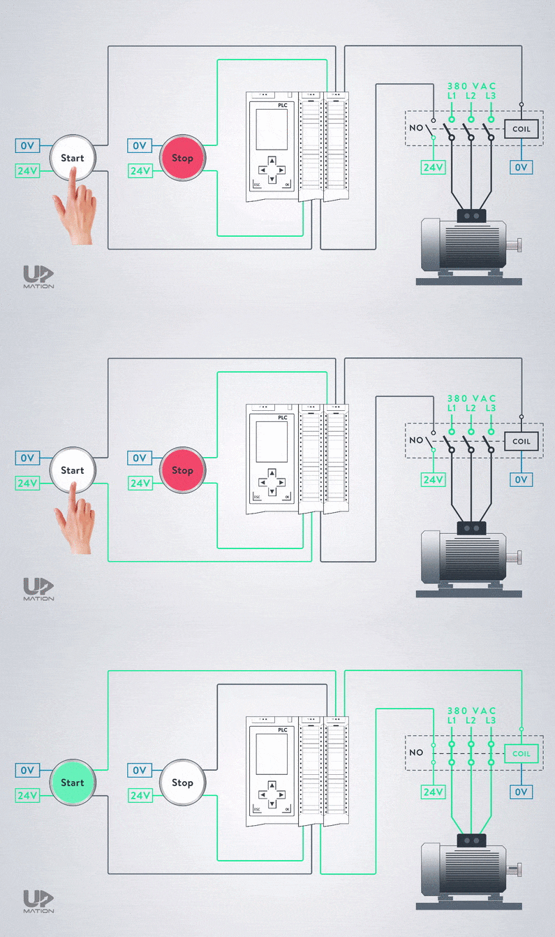
Each of these pushbuttons has an indicator lamp inside to signal the condition of the motor to the operator.
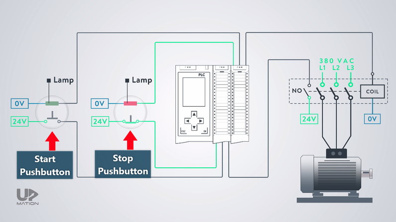
Therefore, we have:
– Two inputs to our digital input card from the pushbuttons
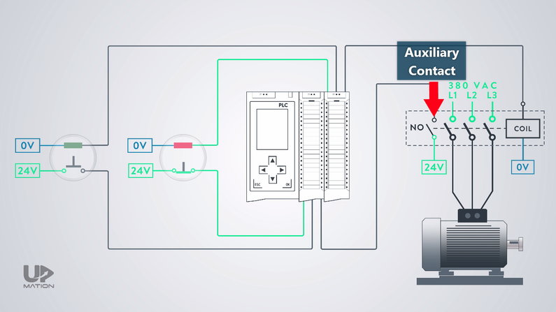
– One input from the contactor’s auxiliary contact

We use the input from the auxiliary contact of the contactor in our PLC program as the feedback for the electric motor status. Is it ON or OFF?
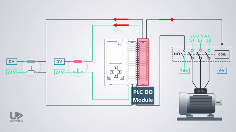
By the way, we have three outputs as well;
– One for turning ON and OFF the electric motor
– Two are for turning ON and OFF the indicator lamps of the pushbuttons
Motor Start and Stop PLC Program
First of all, we should open up the TIA Portal and configure the required hardware including the CPU and PLC cards. You can read Part 1 to know how to do it.
Second of all, we should add the symbols to the tag table according to what I explained in Part 2.
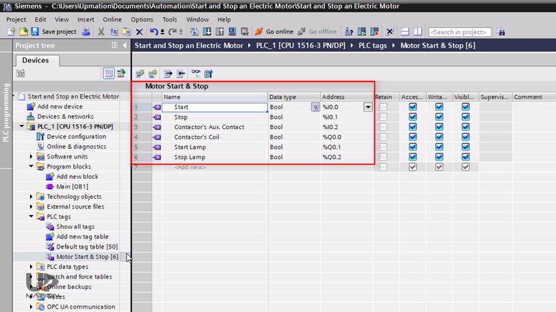
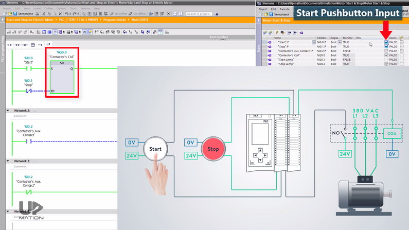
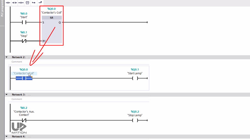
As we have learned in Part 2, from the “Basic instructions” tab, under the “Bit logic operations” folder I drag and drop an SR Flip-Flop and assign the “Motor Contactor Coil” output or Q0.0 to that.
We have explained about Flip-Flops in Parts 2 and Part 3.
I then connect an open contact to the “Set” input of the Flip-Flop for the “Start” push button. And of course, a closed contact to the “Reset” input, for the “Stop” push button.
If you want to know why I used a closed contact for the Stop pushbutton, read this article.
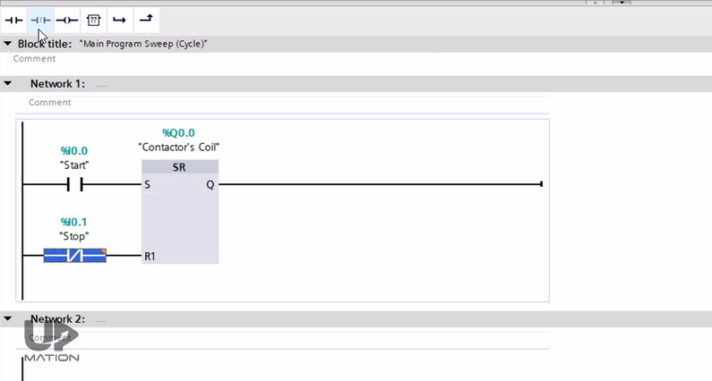
I move on to the Network 2 to add the logic for indicator lamps. When the electric motor is not operating, the “Stop lamp” should be ON and the “Start lamp” should be OFF.
So, here I need the NO contact of the contactor and I assign its input address to this open contact.
Then, I use an Assignment (or output contact) for activating and deactivating the “Start lamp” output.
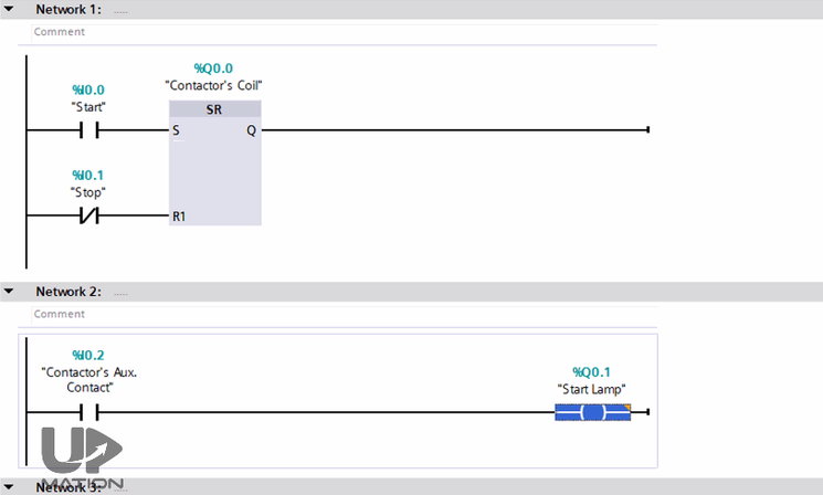
Let’s do the same thing for the “Stop lamp”. So, this time I use a closed contact but with the same address.
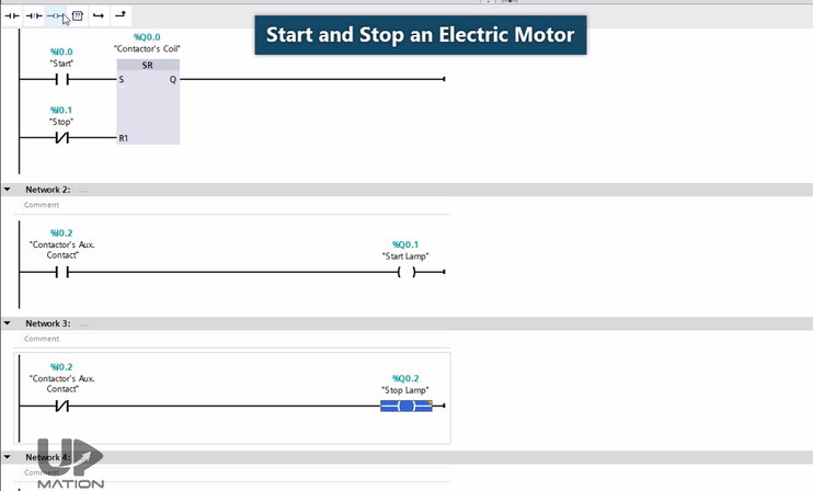
PLC Program NO and NC Contacts VS Actual NO and NC Contacts
There is an important point here.
When the actual physical contact is open, the state of its equivalent PLC logic contacts is like this.
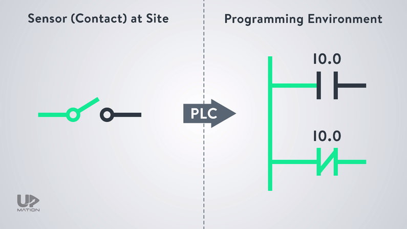
And when it gets closed, its input to the PLC card (which is I0.0, for example) gets active and their state will be updated like this.
So do not confuse the open and closed contacts of the PLC logic with the actual NO and NC contacts.
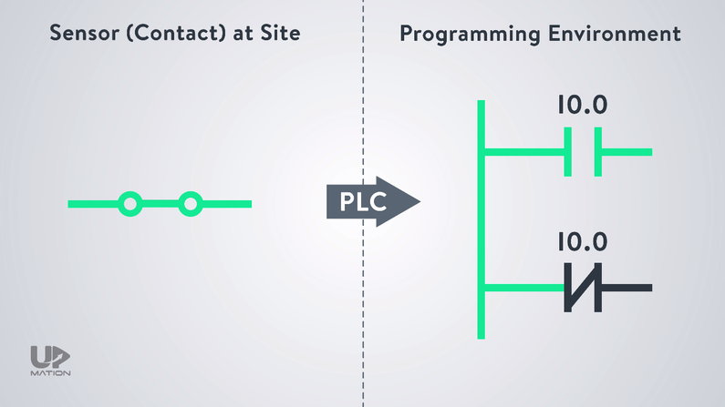
Now, let’s do a quick simulation and discuss another important practical point after that.
Simulating the Motor Start and Stop PLC Program
First of all, we should save and compile the project.
If there was no errors or warnings, we can continue to the next step.
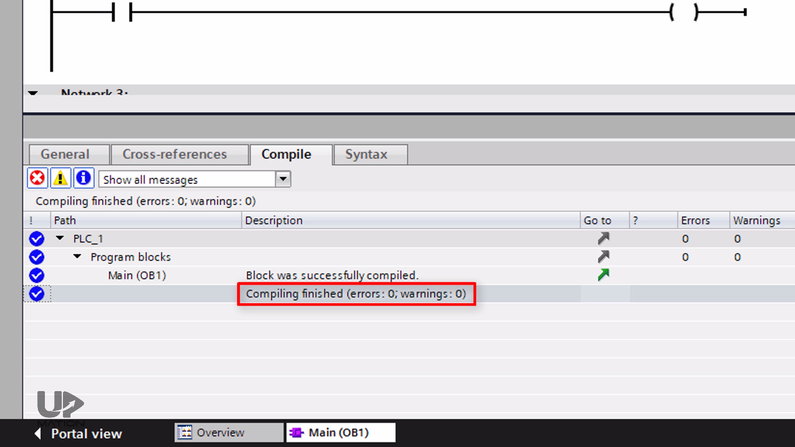
Since in Part 3, we covered the procedure to make the software ready for simulation in TIA Portal, let’s escape this step.
As I explained, the “Stop Pushbutton” has a built-in normally closed contact and in the normal condition, when it’s not pushed, it sends a 24-volt DC signal to the PLC’s input card.
So, I simulate its input to one.
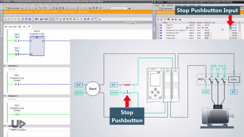
The Start green lamp is OFF and the Stop red lamp is ON and that’s OK.
Let’s start the electric motor by pushing the Start pushbutton. By doing so, the motor starts working.
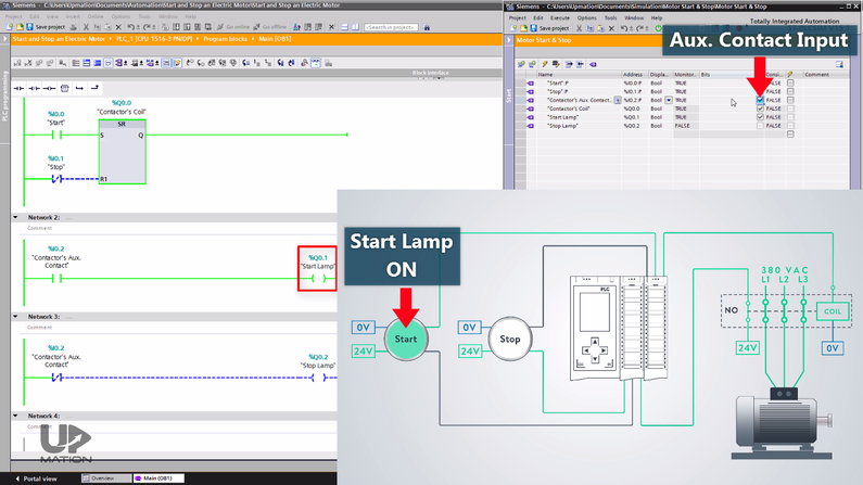
I force the input from the NO auxiliary contact which is I0.2 to True as well. Therefore, the Start lamp turns ON.
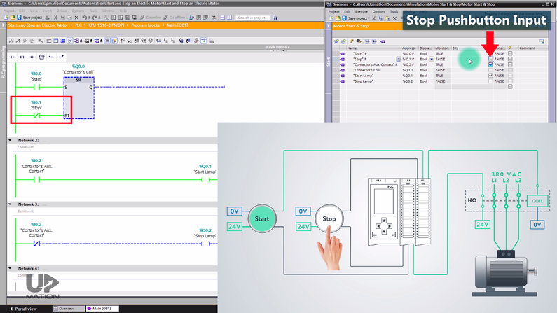
If I push the Stop pushbutton, the motor stops working.
I also should change the state of the NO auxiliary contact to False to change the state of the indicator lamps.
It was quite simple, right?
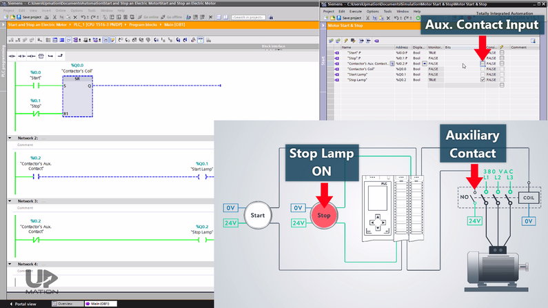
NOTE: For activating and deactivating the lamps, we could also use the contactor’s coil output (Q0.0).
But as you may have guessed it’s not according to the actual situation in the plant where we have to check the functionality of the contactor in our PLC program to see if the electricity is really flowing toward the electric motor via the contactor or not.
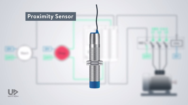
Proximity Sensors in Motor Rotation Monitoring
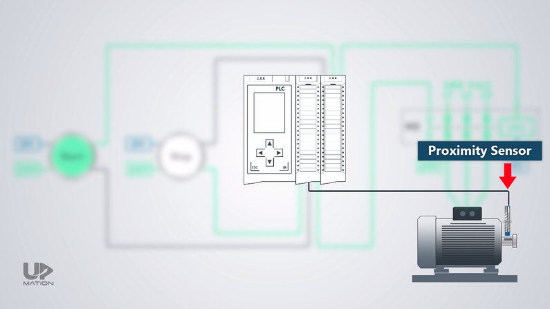
In addition to the contactor functionality check, sometimes where it’s possible, we should use a proximity sensor on the shaft of the motor to make sure if the motor is really running and it’s not stocked by any means.
In this way, as long as the proximity sensor’s input to the PLC card is getting ON/OFF with a certain frequency, we are sure that the motor is working.
Electrical Schematic VS Wiring Diagram
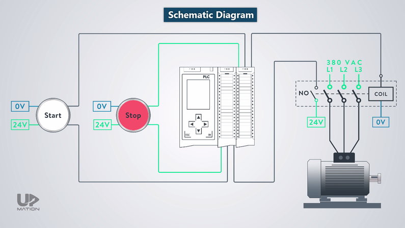
As the last point, one of the important automation documents or drawings that is used frequently during commissioning and troubleshooting of processes is the “Control Panel Wiring Diagram” in which we can find the power and control sections of the process.
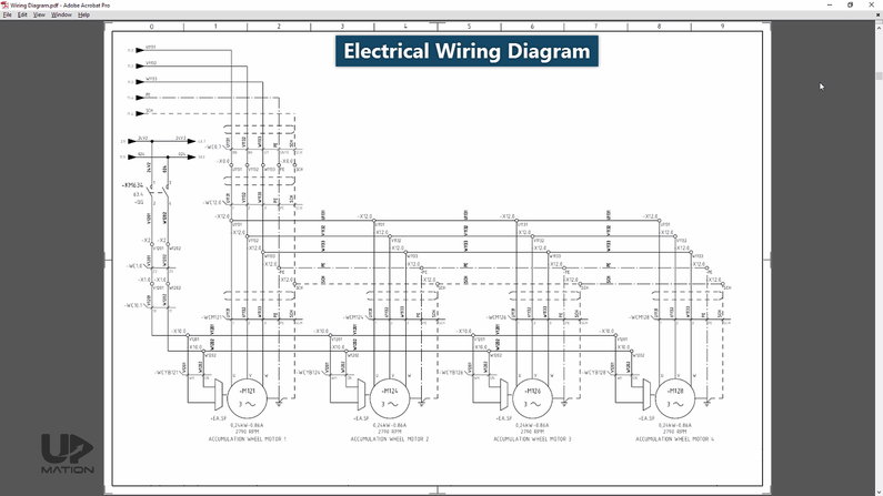
But the schematic that we checked together actually does not really count as a wiring diagram, but it’s a simple schematic drawing for better understanding the concepts.
If you want to learn to read and understand an actual wiring diagram of a real control panel you can read this article.
Thanks for reading another article. Please spread the word by sharing this article:

Good project
Thank you! Happy you liked it! Stay tuned for more.
Great info
Thank you! happy you liked this article!
thank you so much
You’re very welcome, Yaser! Thank you for reading the article.
well doing job clearly and briefly explained
this was very helpful…thank yoiu
You’re very welcome!