Normally Open vs. Normally Closed Contacts
Let’s learn how to choose and use the NO and NC sensors and switches in the industry.
We all know how normally closed and normally open sensors and contacts work and how they differ from each other.
But have you ever noticed that why in emergency push buttons and stop push buttons we always use Normally Closed contacts? Or do you know what is the best solution for being aware of damage in a level switch cable?
In this article, you’ll find out the answer to these questions by some real-world examples and much more about NO and NC contacts.
In a previous video, we have written a PLC program for a process and we have considered all the level switch sensors as Normally Open switches.
But in the real-world conditions when we are choosing the instrument switches or other types of discrete equipment for a process, we have to select which one should be exactly a Normally Open sensor and which one should be a Normally Closed sensor.
Types of Digital Signals in the Industry
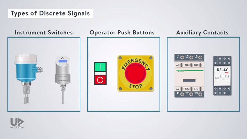
Generally speaking, there are three types of digital or discrete signals in the industry.
– First, the Instrument Switches like Level switches, Flow switches, and so on.
– Second, Operator Push buttons like Start and Stop push buttons, Emergency push buttons, and so on.
– Third, the Digital Feedbacks from Contactors and relays.
The Open and Closed contacts can be integrated into any of these three equipment types.
NO and NC Contacts of a Contactor
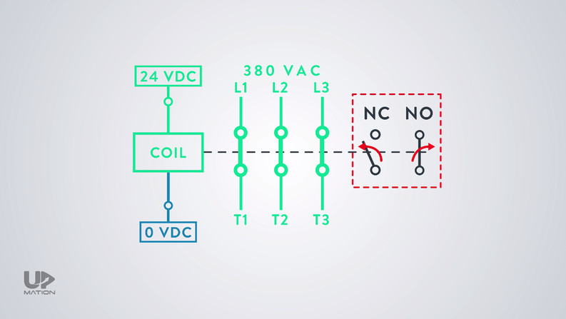
As an example, let’s consider the auxiliary contacts of a contactor.
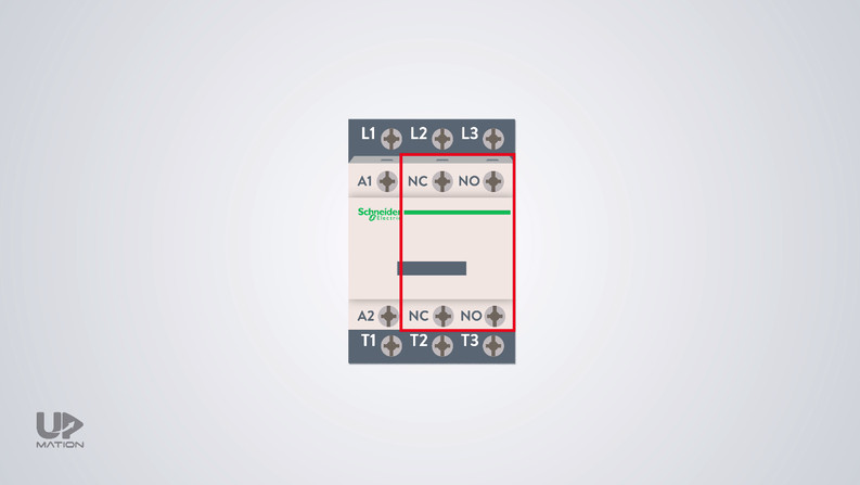
These auxiliary contacts are used to send feedback to the PLC to make sure that the contactor is healthy and operational.
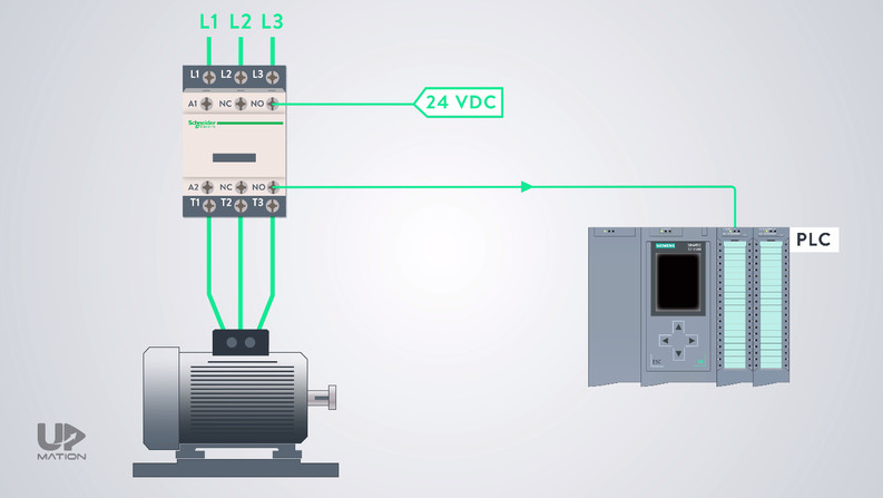
All auxiliary contacts of the contactor maintain their normal condition unless the main coil of the contactor becomes energized.
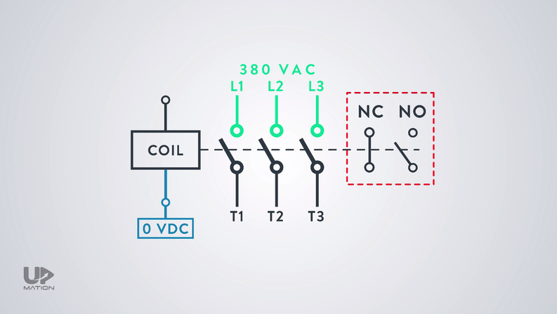
If so happens, all of the auxiliary contacts change their state in a fraction of a second.
The Normally Open contacts will become closed and the Normally Closed contacts become open despite us connecting a voltage to them or not.
NO and NC Contacts of a Sensor
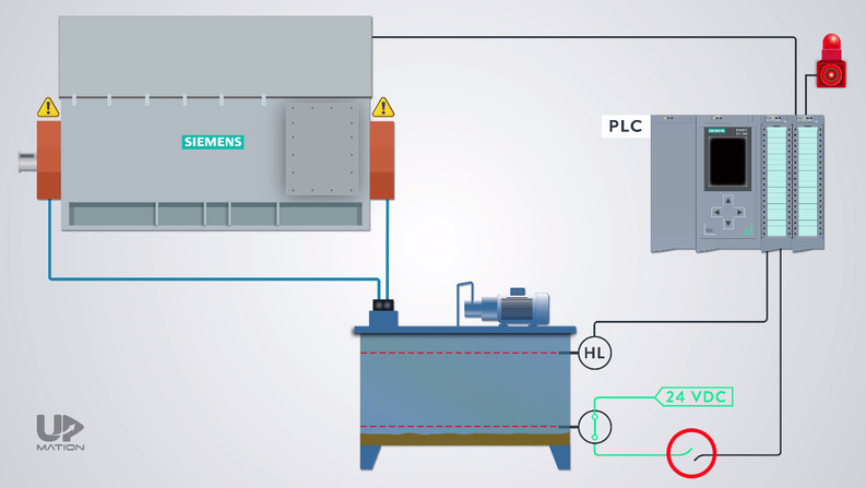
As another example consider this process in which the bearings of a 1MW electric motor are being lubricated and cooled automatically.
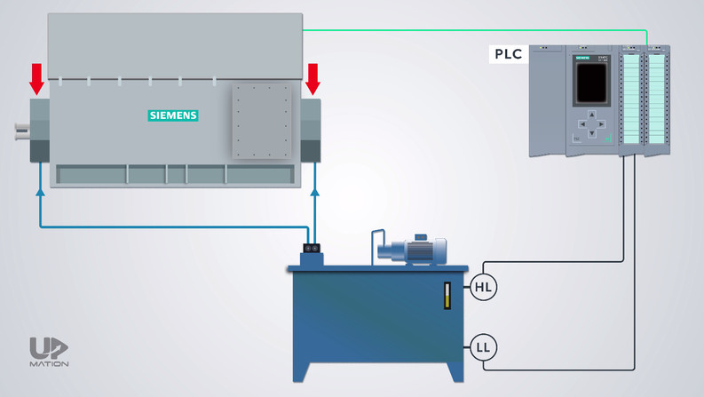
In this case, the normal level of the oil is between the Low and High-level switches.
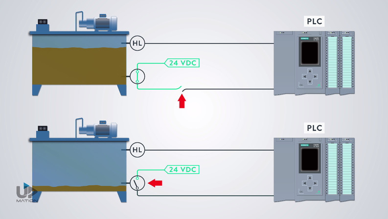
Let’s assume that the Low-level switch of the tank is a Normally Closed switch.
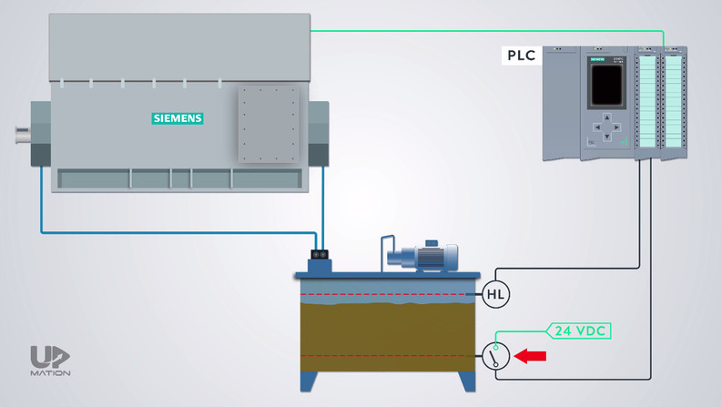
when the oil reaches below this switch (due to leakage for example), it is supposed to send a true signal or a 24-volt DC signal to the PLC.
As a result, the PLC turns off the electric motor.
Simultaneously PLC sends an alarm to operators to become aware of the reason and fill in the tank with oil.
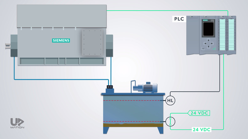
But what if the cable of this level switch is damaged and no one is aware of that?
As you might guess, no one will be informed of the leakage and the low level of the oil inside the tank.
So, the bearings of an expensive electric motor could be damaged due to a wrong selection and design.
Now, let’s consider the Low-Level Switch is a Normally Open one and when the oil level is normal, the switch is sending a 24-V DC signal to the PLC.
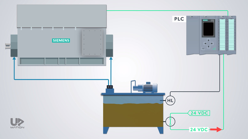
In this case, if we lose the active signal from the low-level switch, due to the cable damage OR because of the oil reduction inside the tank, then everyone will be informed through HMI and safety systems and the electric motor will be shut down instantly.
In this way, the system will be protected correctly.
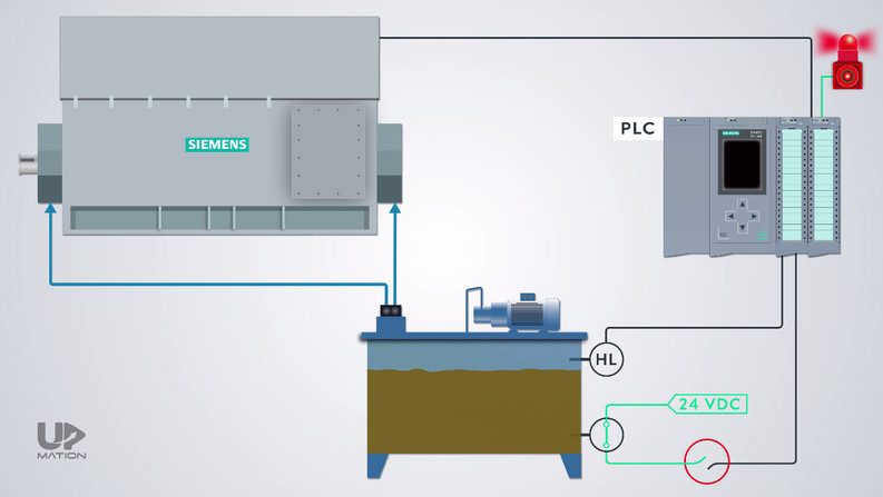
Now, what about the High-Level Switch of the tank? Is it a Normally Closed switch or a Normally Open contact?
Let’s leave this question to discuss in the comments and see what we can learn about the operator push buttons as another type of discrete signals.
NO and NC Contacts of an Operator Push Button
As we mentioned at the beginning of this article, stop push buttons are always considered as normally closed contacts.
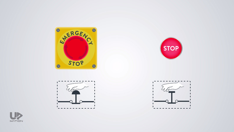
When we activate them, they will open the power circuit and the process will stop immediately.
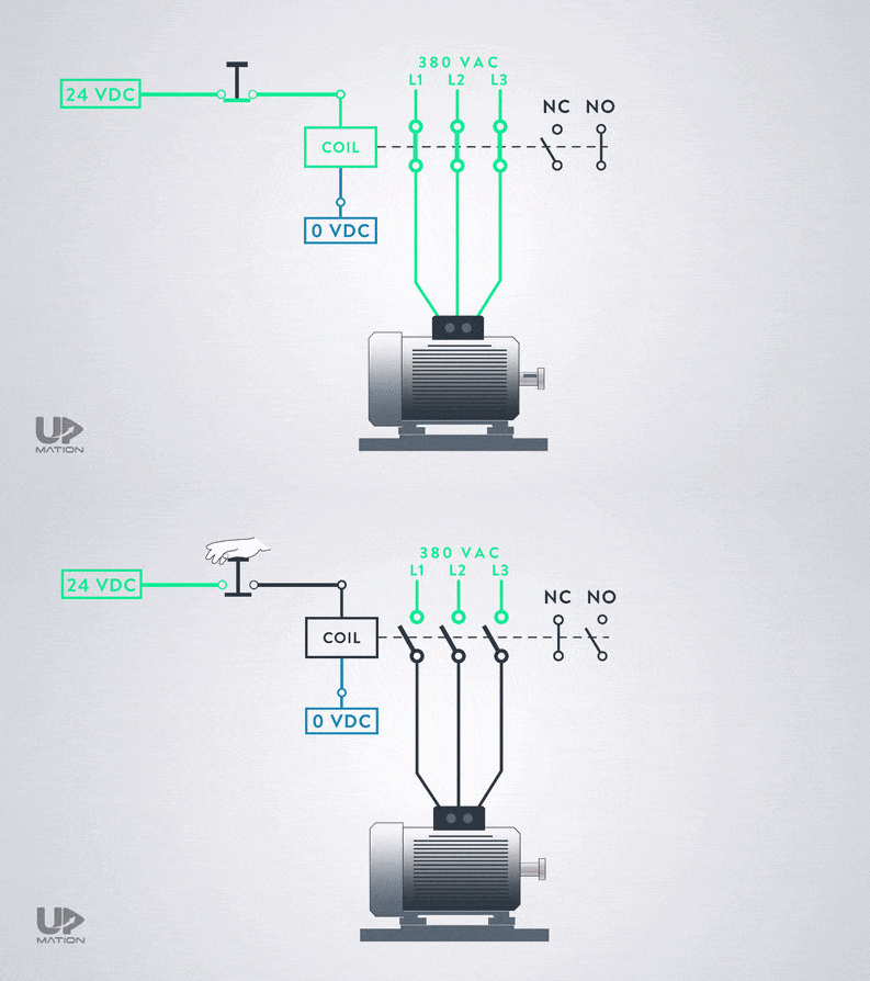
So why normally closed contacts?
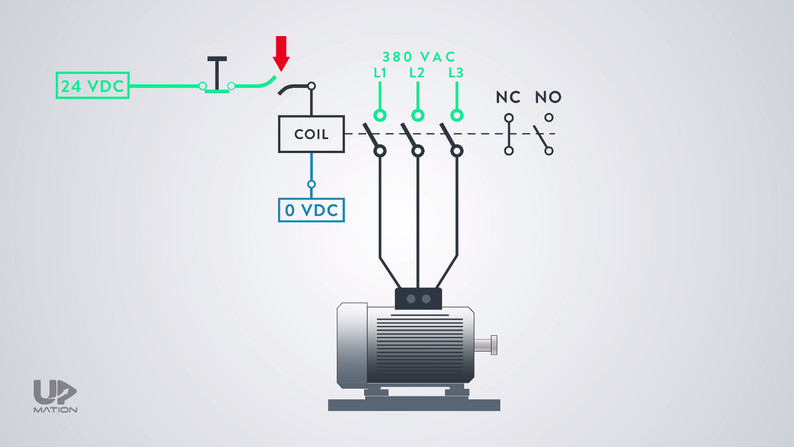
As these types of actuators are mostly used in case of emergency and safety, then we should always be confident about their circuit functionality.
To do so, we use normally closed contacts, and therefore the same as the previous example, when any cable damage happens, the circuit will be opened and the process will be stopped.
Having our process stopped is far better to risk and run the process with a non-functional emergency circuit.
What is a NAMUR Sensor (Switch)?
As the last point, in all of these examples that we have reviewed together, the PLC cannot distinguish the cable damage from changing the pushbutton status or instrument switch status.
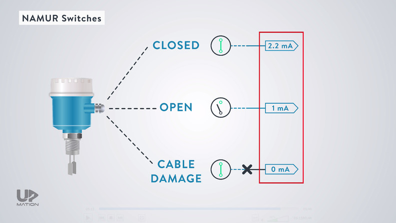
In this case, we can use a specific type of switch called the NAMUR switch.
I should briefly say that a NAMUR switch is a type of switch mainly used for hazardous areas to limit the voltage and current and therefore prevent sparking during the switching.
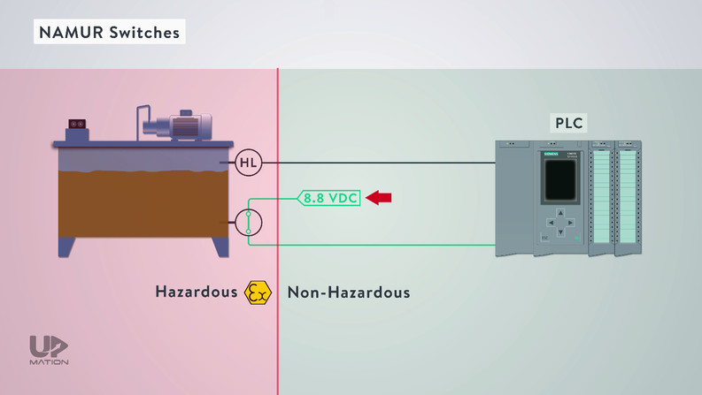
The NAMUR switches are based on milliampere signaling and not voltage levels.
OK, that’s it for this post. Thanks for reading another article. Please spread the word by sharing this article:

Very good explanation.
Thank you! Happy learning!
Nicely explained
Great site one can understand the concept easily
Hey! Happy to hear that! Thank you for the feedback.
Excellent .
Thank you! Happy you liked it.
I’m going through almost all your articles. Well explained, easy to understand, nice graphic and videos. Well done guys, you’re doing an amazing job!
Would be great to have some more details about electrical wiring.
Hi Paolo! Thank you very much for your comment! I’m really happy you enjoyed it this much.
Sure thing! We actually planned for more videos about wiring diagrams in near future. Please stay tuned.
I love this explicit explanation guys.But just to further clear my doubt on the first aspect which is the low level switch ,are you concluding that the NC is the appropriate? Bcs your last explanation (on the emergency stop)referencing the first one on the LL switch complicates me a bit.You want to clear that please?
Hi, Alusine! Thank you for leaving your comment. About your question:
The Low-Level Switch (LLS) of the tank should be a NO sensor. And why is that?
In this way, whether;
1. The sensor is not excited by the oil (The oil level is low) or
2. Sensor’s cable is damaged and disconnected from the PLC’s input card (either the oil level is low or normal),
In both cases, the 24-Volt signal from the sensor is not reaching to the PLC card. Therefore, the operator will be informed that something is wrong (either it is the oil level or the sensor damage)
In the next example (Pushbuttons), we are not referring to any specific case in the oil tank; just trying to say that in any sort of application, we have to think and consider the best type of contact that fits the situation.
Nice review
Thank you! Happy you liked this article.
I am working on a lube oil tank that uses three level switches.
High, Low and a Low Low cutoff.
They have a chain and weight arrangement.
With the tank empty, all three switches are hanging and are all activated (weight of chain closes contact).
Should level switches be in their normal state with no simulation ie no level?
Hi, Ryan!
In my opinion, it was better to choose at least a float switch for each level and consider the LowLow and Low Switches as NO and the High-level switch as NC. But in this case, I don’t know how you’re going to simulate the situation for each level and reverse their function. In most cases, it is not possible (or recommended) to do such things. Let’s discuss this further in case you have more questions or ideas.
That was very nice example and illustration 🙂
Thanks.
Hey! Happy you liked it! You’re very welcome and thank you for watching.
Please share this video with your friends or colleagues on social media.
Why does a contactor have both a aux-NC and aux-NO? Perhaps this is to increase the robustness of the control circuit to loss of signal (damaged cable) ?
So, to verify the coil is activated, the PLC should verify +24V on the aux-NO circuit? And to verify the coil is inactive, the PLC should verify +24 on the aux-NC circuit? Is that correct? Does the PLC typically just look at one of the signals, as I described, or does it typically check for the status of both aux circuits, to verify one is closed AND one is open?
Thanks!