What is an Electromechanical Relay and How to Use it?
Why and How to Use a Relay
Have you ever asked yourself “why we use a relay?” In this article, you’ll get some answers to this question!
In this article, you’ll first get to know about Electromechanical relays that are the most used types of relays.
Then, you’ll see how electric relays work and learn about the relay wiring diagram.
After all, we’ll answer some questions: What do we use a relay for? How should we wire a relay?
We also talk about the combination of normally open and normally closed contacts of the relays which will shape different types of mechanical relays (SPST, SPDT, etc.).
Different Types of Electrical Relays
As you may know, the relays in the industry are fallen into two main categories:
– Solid-State Relays or SSRs
– Electromechanical relays or EMRs.
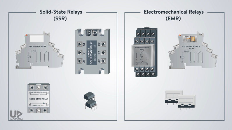
Of course, if you’re an electrician you may face some other types of relays such as safety relays, Power Protection relays, and so on.
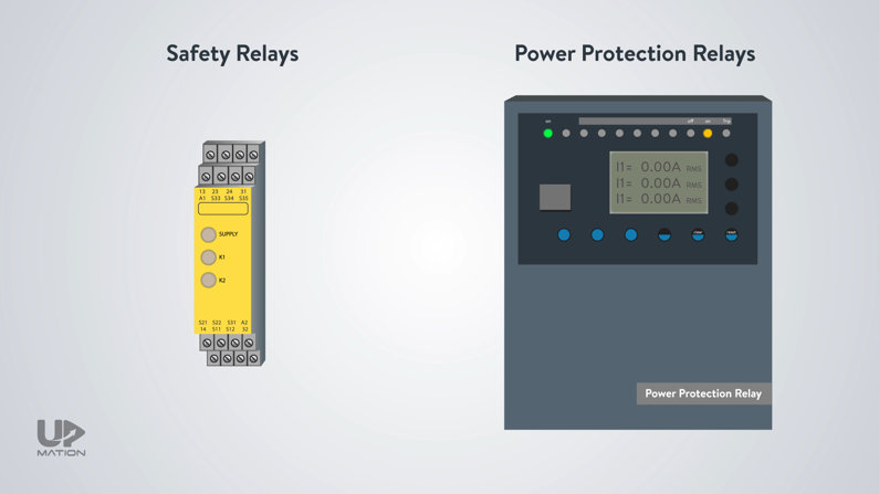
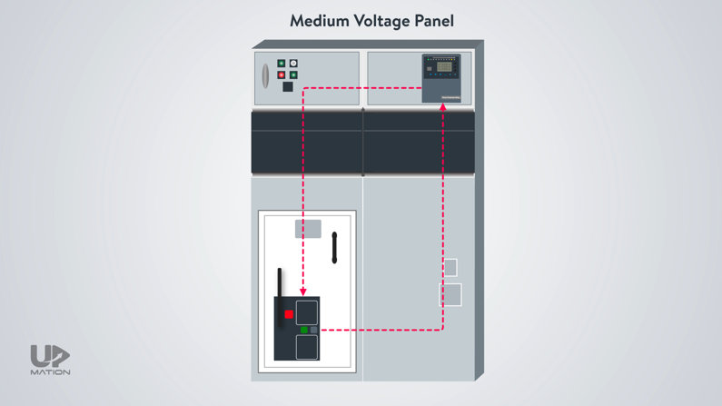
You may see Power relays installed on medium voltage panels and they are a type of protection device for power systems.
They more resemble a controller than a relay! So, we can learn about them in detail in a future article.
You know all about the history of the control panels were made of only relays and contactors and regardless of all technological advancements we still use relays within the control panels.
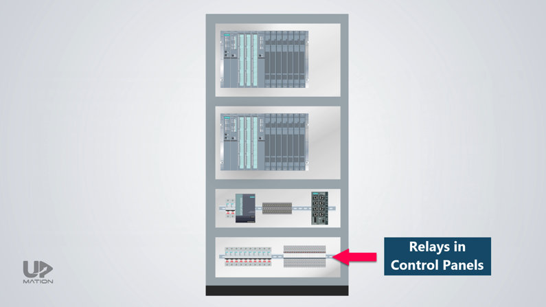
You may ask why we should still use a relay when some PLC cards can switch both the DC and AC loads with different power ratings.
Let’s first quickly see how electromechanical relays work and get introduced to some essential expressions and after that, we’ll answer this good question.
Electromechanical Relays
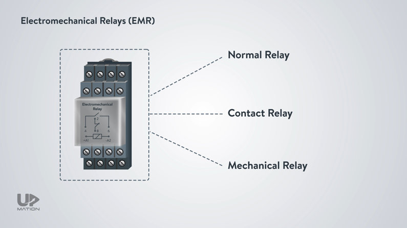
You may hear of electromechanical relays as:
– Normal relays,
– Contact relays,
– Mechanical relays,
and so on.
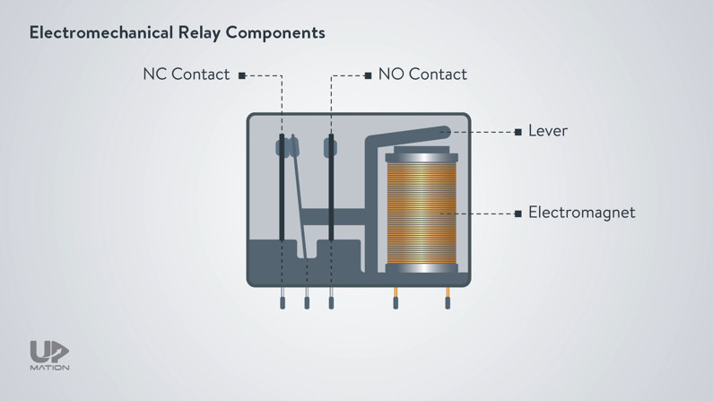
Electromechanical Relay Components
If we look to a cube type mechanical relay, we see this:
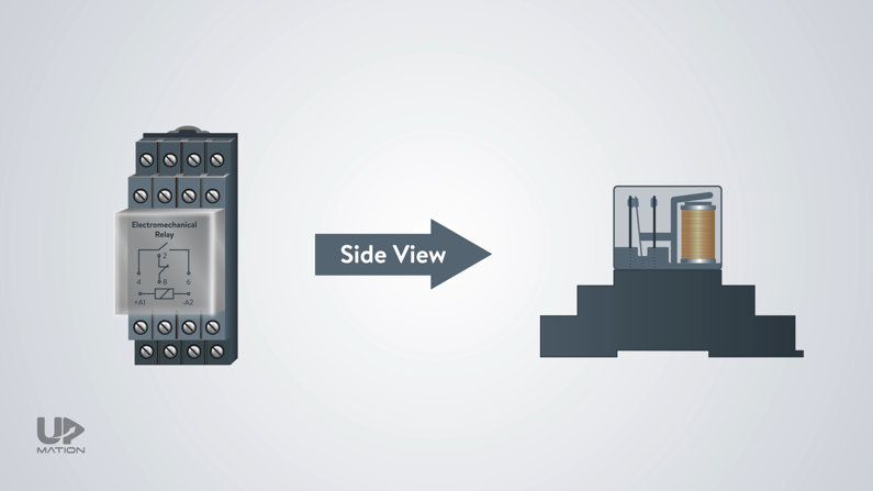
An electromechanical relay uses a mechanical mechanism to move a lever and change the position of some contacts.
This movement is made possible by an Electromagnet.
Electromechanical Relay Operation
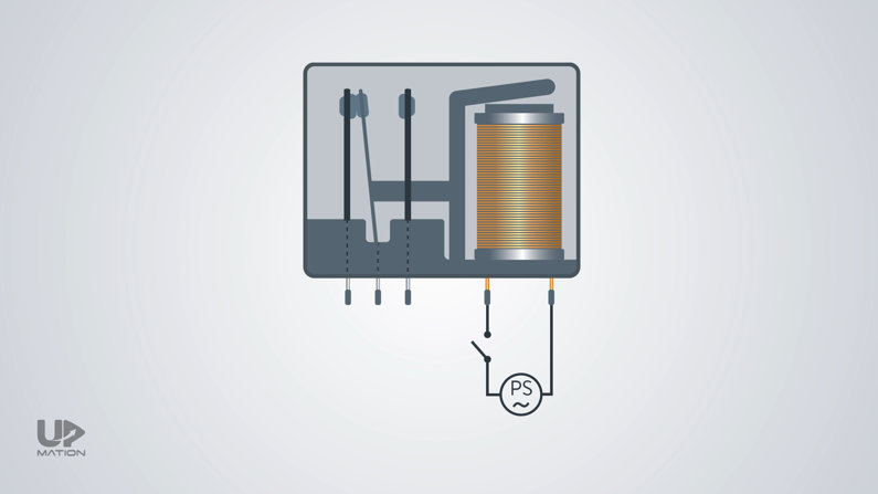
When we connect the power to the magnet, it attracts the lever and therefore the NO and NC contacts change their normal or non-energized position.
You can learn more about NO and NC contacts from this article.
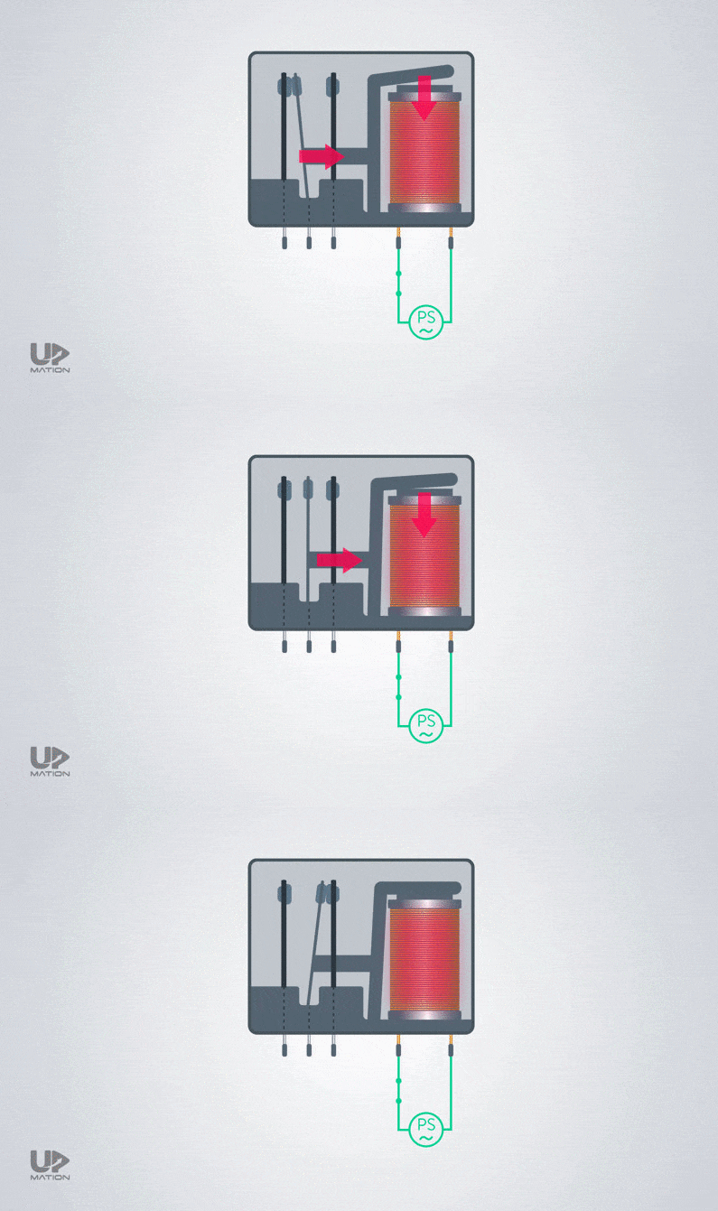
When the power gets disconnected from the coil, the lever and the contacts will get back to their initial position.
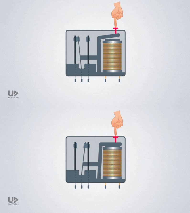
Also, there is a pushbutton on the relay that we can push and test the relay manually, without connecting and disconnecting the electrical power.
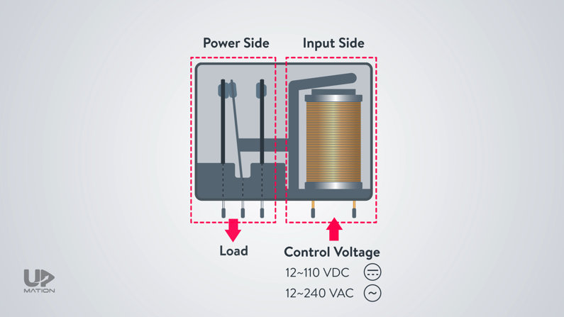
So far, we have discussed the input or primary side of the relay that we connect the control voltage to that. This control voltage is usually from 12 to 110 volts DC, or it could be from 12 to 240 volts AC.
But what about the power side of the relay? Let’s learn a little bit about the relay wiring diagram here.
Electromechanical Relay Wiring Diagram
The power side or secondary side of the relay will be connected to a consumer or let’s say a “load”.
Electromechanical relays in particular are usually used in single-phase applications.
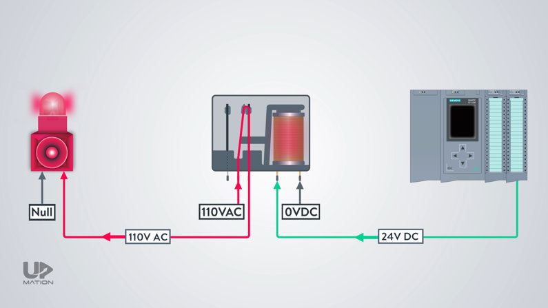
Within an electrical control panel, we use them to connect the channels of the PLC digital output card to single-phase AC low power rating actuators and devices such as solenoid valves, lamps, Siren alarms, and so on.
We should select the relay in a way that it will match the specifications and power rating of the load as well as the control voltage we’re going to apply to its coil.
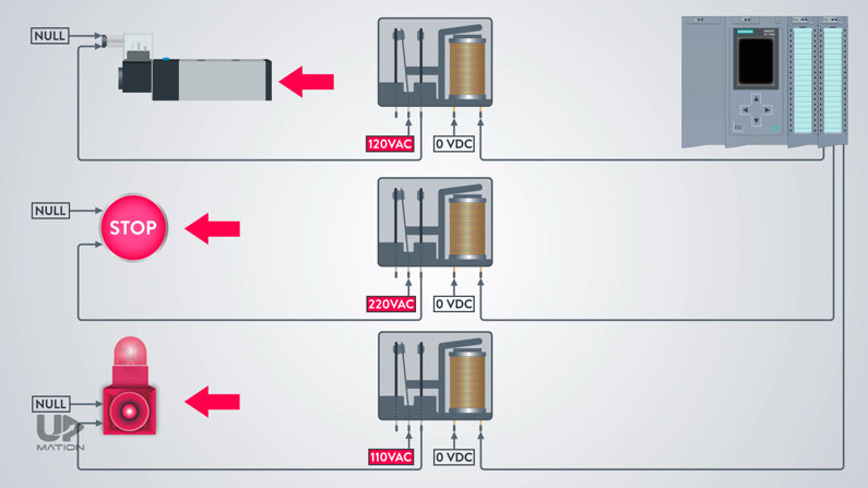
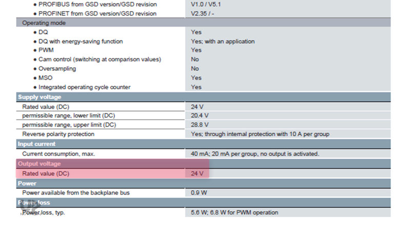
For instance, if we want the PLC to turn on a Siren alarm according to its logic, we should first check which control voltage signal the PLC card sends out.
As you see it’s a 24-Volt DC signal.
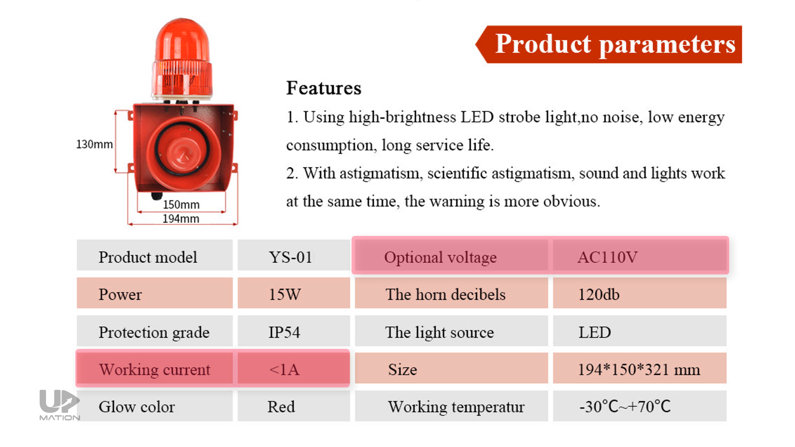
Then we’ll check the Siren’s power rating; for example, it is 110 volts AC with about 1 amp of rated carry current.
So we should make sure of our relay’s coil voltage and the amount of electrical current that its contacts can carry.
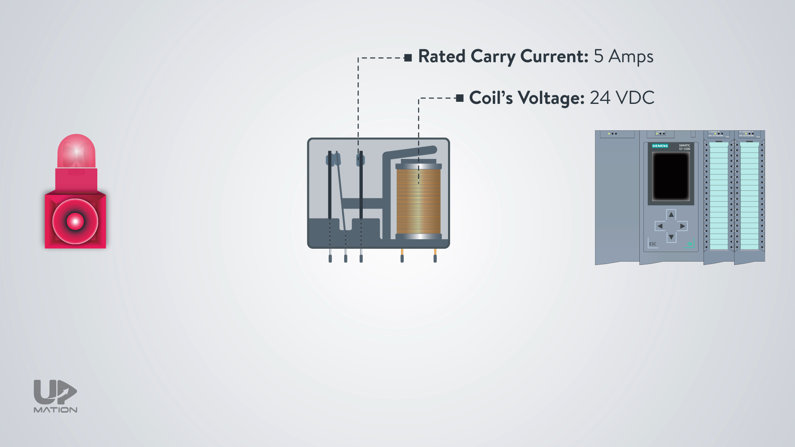
Then we connect the 110 AC voltage from the power supply to the relay’s “common” connection. And from there we connect the normally open contact of the relay to the Siren alarm.
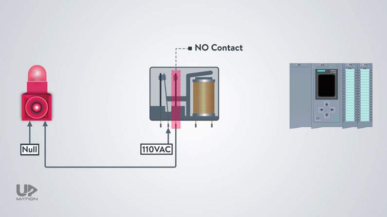
Therefore, when the PLC sends the 24 VDC signal to the relay, the NO contact gets closed and the AC voltage will be transmitted to the Siren.

So here is the answer to the question; Why we should still use a relay rather than solely using a PLC card?
Why We Use Relay in PLC Applications
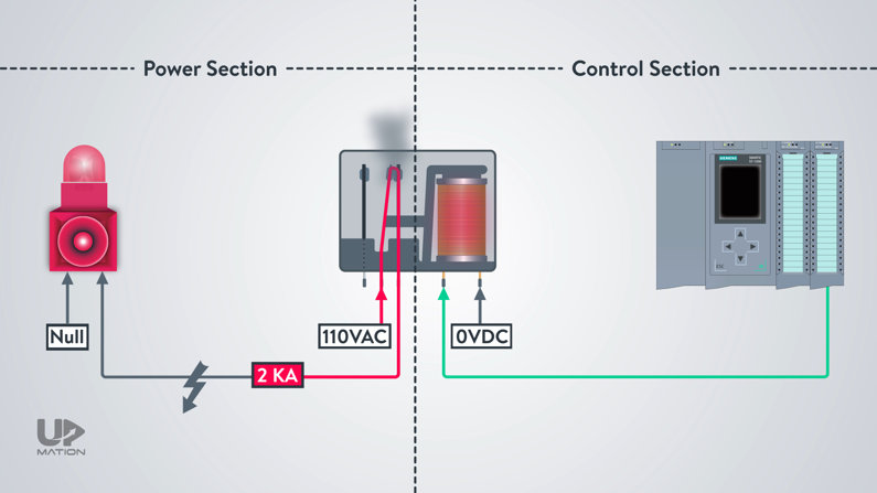
In this example, we used a 24 VDC control power coming from a PLC digital output card to command to a device with a different level and type of voltage on the other side of the relay.
You may say we can choose a PLC card that can switch even the high-rated current loads with 110 AC voltage. Now what?
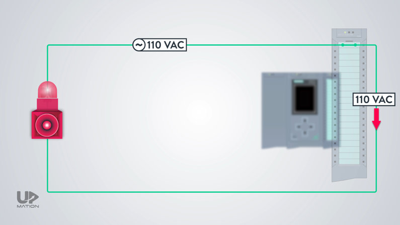
You may notice that, we simultaneously isolated or completely separated our control part of the circuit from its power section to prevent damaging our PLC card in case of short-circuit failures.
I’ll tell you the cost is a more important factor here. Both the cost of a PLC card with high power rating contacts and the cost of its maintenance in case of high short circuit failures.
It’s more reasonable to change a broken 20-dollar relay than changing a 1000-dollar PLC card, isn’t it?
Now that you’ve got your answer, let’s see which types the electromechanical relays have.
Different Types of Electromechanical Relays
1. Different Types of Mechanical Relays (by their Contacts)
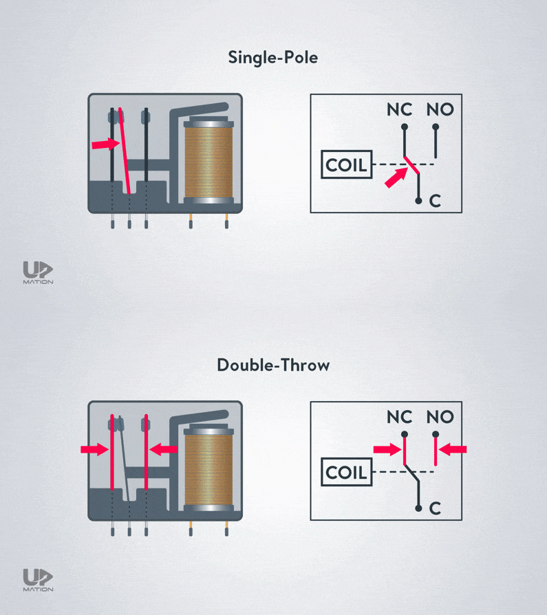
We can classify the Electromechanical relays according to the number of their NO and NC contacts. The standard categories are:
– SPST relay or Single Pole, Single Throw.
– SPDT relay or Single Pole, Double Throw.
– DPST relay or Double Pole, Single Throw.
– DPDT relay or Double Pole, Double Throw.
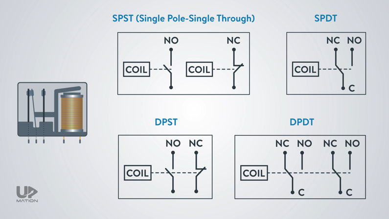
For example, this is a Single Pole, Double Throw, or an SPDT contact type.
2. Different Types of Mechanical Relays (by their shape)
The EMRs have different types:
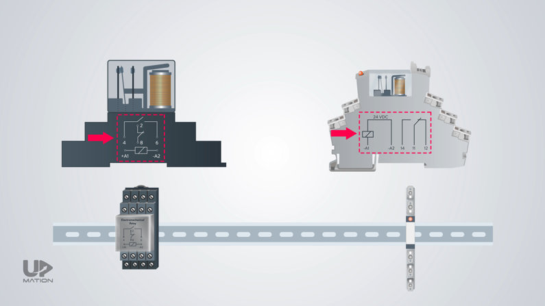
– Ordinary cube types to mount on a DIN rail within a control panel.
– Slim types to mount on a DIN rail within an electrical control panel.
– Miniature types to solder on a PCB.
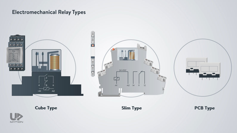
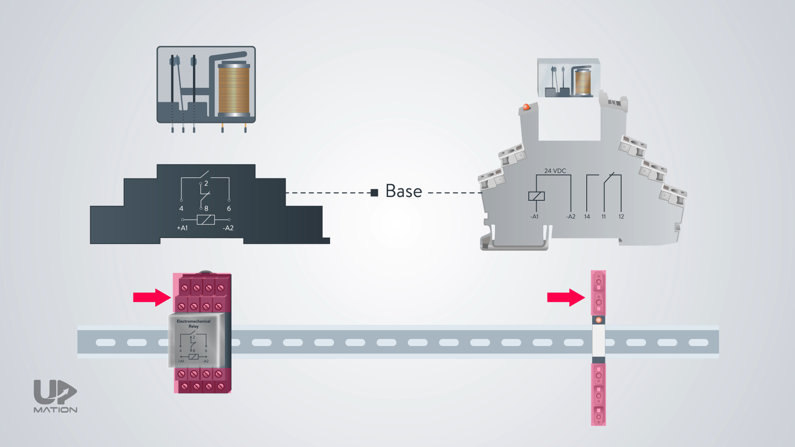
The ones we install on a DIN rail has made of two separate parts;
One is the base that is an interface to connect the wires to the coil and the contacts.
The other one is the head, housing the coil and the contacts.
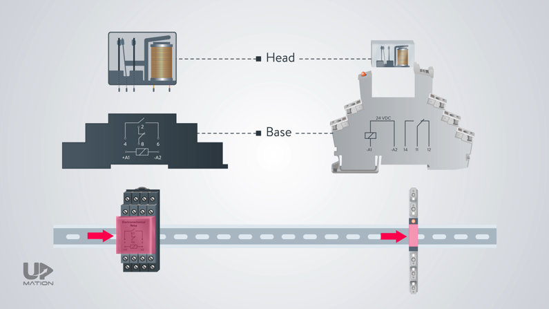
We can dismantle and assemble the relay easily by pushing the headpins into the base.
You can always find a simple relay connection diagram, the coil voltage, and the other specifications on the head part or just on the side of the relay and you should use them as your connection guide when you are wiring the relay.
And… that’s it! This time YOU let us know what you would like us to cover for the next articles.
Thanks for reading another article. Please spread the word by sharing this article: