How Solid State Relay Works

How Solid State Relay Works

How Solid State Relay Works

What are Solid State Relays and how should we use them in practice? These are some of the questions we’ll answer in this article.

In a previous article, we have discussed the ins and outs of the Electromechanical relays which I strongly suggest you to check that first from here.

In that article, you’ve learned why we still better use the relays in general, regardless of the great advancements in technology.

In this article, we investigate a fully electronic type of relay; the Solid State Relay or SSR for short.

We check to see how to test a Solid State relay with multimeter and then you learn about Solid State relay wiring. After we checked differences between various types of SSRs you’ll also learn how to choose among all different types of SSRs depending on a given application.

What is a Solid State Relay and Why do we Use Them?

The look is quite a bit different from electromechanical relays; the same as its manufacturing technology.

Solid State Relays

As it’s mentioned, there is no mechanical moving part used in Solid State relays manufacturing and all are made of semiconductors such as diodes, Transistors, Thyristors, Triacs, and so on.

Solid State Relays

There are different designs for different usages.

For example, when you’re designing an electrical control panel’s internal layout, you always need more space.

And there is a slim design for Solid State Relays that would be an appropriate choice for you!

Solid state relays din rail mount

If you replace the EMRs with the slim design of the SSRs then you’ll have more spare space in your panel to add more hardware.

Power Protection Relays on Medium Voltage Panels

You can use Solid State Relays as an interface between your PLC output cards and the loads out there in the process.

What is the purpose of solid state relay

However, as you’ll learn in the future articles, the Thyristors, and Triacs are more intended to drive the resistive heating elements and therefore the Solid-State Relays which use these electronic parts in their output circuits, are also more applicable for these purposes.

What is a solid state relay

They also have different names depending on their manufacturer. For instance;

– Photo Relays,

– MOSFET Relays,

– Solid State Modules,

– Solid State Drives,

and so on.

How to Test a Solid State Relay with Multimeter

The relay we have chosen for this example is a single-phase relay that accepts a fixed DC voltage on its input terminals and has only a Normally Open contact on its output.

It’s input is ranging from 3 to 32 volts DC.

How to check Solid state relay

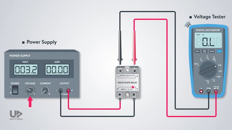
By doing a continuity test using a power supply and a voltage tester (or Multimeter) we make sure of the functionality of the Solid State relay.

First off, we should adjust the tester for the continuity test.

How to test a solid state relay with multimeter

Then, I place the probes on the output terminals of the relay.

As soon as the input voltage reaches the 3 volts or above, you can hear a sound from your tester saying the resistance between the probes is almost zero so the electronic output contact has been closed.

How to test solid state relay using multimeter

How does a Solid State Relay Work? (Solid State Relay Wiring)

On the output side of the relay, we see that we can connect a 24 to 480 volts AC load.

Let’s assume that there is a 600-watt/230-Volt heater (Heat Tracing) that we want to use as the load and control the temperature using a control signal coming from a PLC.

NOTE: In a future article, you’ll learn that SSRs are usually used with another type of controller, known as the PID controller.

SSR PID temperature controller

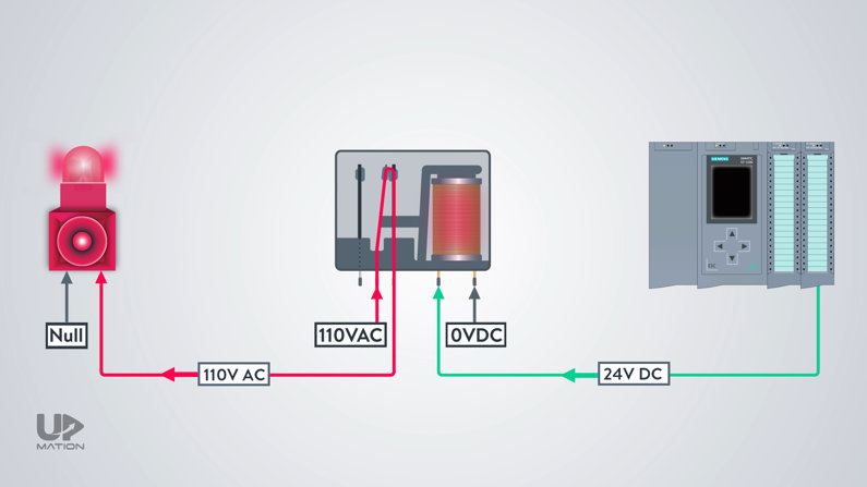
The heater will get its power from the AC power source but via the SSR. We transfer the live wire to the heater via the SSR.

So, we connect the Live wire from the power source to one of the output terminals of the SSR and will wire its other terminal to the heater.

The Neutral wire will be directly connected to the heater from the power source.

Here, you have to make sure to cover the terminals of the SSR as it has electrical power all the time; even when the relay output is switched off.

Solid state relay wiring

As soon as the PLC sends the command, the SSR LED turns on, showing the output of the relay is closed.

So, the heater turns on and starts warming up to increase the temperature.

How to wire a solid state relay

Of course, there is a sensor to feedback the temperature of the tank to the PLC.

How to use solid state relay

Solid State Relay vs. Mechanical Relays

1. High-Speed Switching SSRs

Consider a process in which we’re gonna send commands to a load in a matter of milliseconds.

In this process, the speed of switching gets a major parameter for us.

So, we’ll benefit from the semiconductor technology of the Solid State relays as they are WAY faster than electromechanical relays.

Solid State Relay Advantages

2. No Sparks, Low Noise!

As you may already know, the millivoltage signals, such as the signals from the Thermocouples can be corrupted by the electrical noise.

Whenever an electromechanical relay switches on or off, it produces some electrical noise in the panel, and the more the electromechanical relays are, the more could be the noise and the chance of corrupting our signals in the control system.

So, we better use the SSRs as they emit far less electrical noise.

Solid State Relays produce no Sparks

3. Hazardous Area Compatibility

In a hazardous area, you HAVE TO use the SSRs;

Because the generated sparks from an EMR switching, could be very dangerous and lead to an explosion.

Solid State Relays for Hazardous Areas

Apart from single-phase, three-phase, slim, or PCB types of SSRs, they fall into three main categories according to their output switching modes.

Types of Solid State Relays

1. Random Turn On Solid State Relay (Asynchronous)

The first one is the “Random Turn-On” SSR or “Asynchronous” Solid State Relay.

When the controller applies the control voltage to the input terminals of the relay, the relay output will turn on immediately after that and fully pass the current toward the load.

Random Turn On Solid State Relay

2. Zero Crossing Solid State Relay (Synchronous)

The second and the most common type is the “Zero-Crossing” or “Synchronous” type.

What is zero-crossing?

In an Ac sine wave, whenever the wave crosses the horizontal axis, we’ll have a zero-crossing point.

Zero Crossing Point Definition

So, in this type, as opposed to a “Random Turn-On” type relay, when the input is active, it does not conduct the load current immediately;

but the output will wait for the first zero-crossing point of the AC load voltage, to pass the whole electrical current toward the load.

Zero Crossing Solid State Relays

In both “Random Turn-On” and “Zero-crossing” types of SSRs, when the control voltage is removed from the input terminals, the output will not stop passing the load current until the next zero-crossing point of the wave reaches.

It is a characteristic of all types of solid-state relays regardless of their switching type.

Zero crossing vs random turn on

3. Proportional Control Solid State Relay

The third type of SSRs are named “Proportional Control” Solid State Relays and have their own different types. The most common types of them are:

– Phase-angle Relays

– Burst-fire Relays

Proportional Control SSRs are used for extremely precise control of the output (especially in heating and lighting applications).

Proportional solid state relay

In Proportional Control SSRs, the controller will apply an ANALOG control signal to the input of the SSR instead of a fixed DC or AC control signal.

So, the control signal could be an analog voltage signal such as 0-5- or 0-10 volts DC or it could be an electrical DC current such as 4-20 mA.

The output will vary the amount of the load current depending on the amount of the control signal on the input side.

Types of solid state relays

3.1. Phase-Angle Proportional Control Solid State Relay

Let’s assume we have a “phase-angle” SSR that accepts a 0-10 volts signal on its input terminals.

The controller applies a 5-volt control signal to the SSR input for transmitting 50% of the power to the load.

As a result the SSR output (which is a Triac) will turn on at the peak of every AC half cycle and therefore conducting 50% of the power to the load.

Phase Angle Solid State Relay

3.2. Burst-Fire Proportional Control Solid State Relay

As another example, this time, we have a “burst-fire” SSR with again a 0-10 volts DC analog control signal.

If the controller applies 70% of the input signal (which is 7 volts here), then the output AC voltage would conduct 70% of the total power to the load.

It means, from every 10 cycles of the AC voltage, only 7 cycles will pass toward the load.

Burst Fire Solid State Relay

These were the simplified waveform for almost all common types of SSRs.

Which SSR for Which Application?

Selecting the correct type of solid-state relay allows great precision in process control.

For “Resistive loads” like heating elements the Zero-crossing and Proportional Control SSRs are perfectly suited.

For “Inductive loads” such as electric motors, contactors, and so on, the Turn-On type SSRs are usually a better fit.

Solid State Relay Applications

In the future lesson, we’ll show you an example of a Zero-Cross type SSR in practice and you’ll understand why it is essential to choose the correct type of SSR depending on your application.

And… that’s it! This time YOU let us know what you would like us to cover for the next articles.

Thanks for reading another article. Please spread the word by sharing this article:

Our YouTube Channel

Contact Us

Have a question or suggestion?

[email protected]

Youtube channel

What is an Electromechanical Relay and How to Use it?

What is an Electromechanical Relay and How to Use it?

Why and How to Use a Relay

Have you ever asked yourself “why we use a relay?” In this article, you’ll get some answers to this question!

In this article, you’ll first get to know about Electromechanical relays that are the most used types of relays.

Then, you’ll see how electric relays work and learn about the relay wiring diagram.

After all, we’ll answer some questions: What do we use a relay for? How should we wire a relay?

We also talk about the combination of normally open and normally closed contacts of the relays which will shape different types of mechanical relays (SPST, SPDT, etc.).

Different Types of Electrical Relays

As you may know, the relays in the industry are fallen into two main categories:

– Solid-State Relays or SSRs

– Electromechanical relays or EMRs.

Types of Relays

Of course, if you’re an electrician you may face some other types of relays such as safety relays, Power Protection relays, and so on.

Types of Relays electrical

You may see Power relays installed on medium voltage panels and they are a type of protection device for power systems.

They more resemble a controller than a relay! So, we can learn about them in detail in a future article.

Power Protection Relays on Medium Voltage Panels

You know all about the history of the control panels were made of only relays and contactors and regardless of all technological advancements we still use relays within the control panels.

Relays in Control Systems

You may ask why we should still use a relay when some PLC cards can switch both the DC and AC loads with different power ratings.

Let’s first quickly see how electromechanical relays work and get introduced to some essential expressions and after that, we’ll answer this good question.

Electromechanical Relays

You may hear of electromechanical relays as:

– Normal relays,

– Contact relays,

– Mechanical relays,

and so on.

Electromechanical Relays

Electromechanical Relay Components

If we look to a cube type mechanical relay, we see this:

Mechanical Relay

An electromechanical relay uses a mechanical mechanism to move a lever and change the position of some contacts.

This movement is made possible by an Electromagnet.

Electromechanical Relay Components

Electromechanical Relay Operation

When we connect the power to the magnet, it attracts the lever and therefore the NO and NC contacts change their normal or non-energized position.

You can learn more about NO and NC contacts from this article.

Electrical Relay

When the power gets disconnected from the coil, the lever and the contacts will get back to their initial position.

Electromechanical Relay Logic

Also, there is a pushbutton on the relay that we can push and test the relay manually, without connecting and disconnecting the electrical power.

Electromechanical Relay Operation

So far, we have discussed the input or primary side of the relay that we connect the control voltage to that. This control voltage is usually from 12 to 110 volts DC, or it could be from 12 to 240 volts AC.

But what about the power side of the relay? Let’s learn a little bit about the relay wiring diagram here.

Electromechanical Relay Wiring Diagram

The power side or secondary side of the relay will be connected to a consumer or let’s say a “load”.

Relay Diagram

Electromechanical relays in particular are usually used in single-phase applications.

Within an electrical control panel, we use them to connect the channels of the PLC digital output card to single-phase AC low power rating actuators and devices such as solenoid valves, lamps, Siren alarms, and so on.

We should select the relay in a way that it will match the specifications and power rating of the load as well as the control voltage we’re going to apply to its coil.

Relays for Dummies

For instance, if we want the PLC to turn on a Siren alarm according to its logic, we should first check which control voltage signal the PLC card sends out.

As you see it’s a 24-Volt DC signal.

PLC Output Card Voltage

Then we’ll check the Siren’s power rating; for example, it is 110 volts AC with about 1 amp of rated carry current.

Siren Alarm Power Specifications

So we should make sure of our relay’s coil voltage and the amount of electrical current that its contacts can carry.

How a Relay Works 12v

Then we connect the 110 AC voltage from the power supply to the relay’s “common” connection. And from there we connect the normally open contact of the relay to the Siren alarm. 

Electric Relay Diagram

Therefore, when the PLC sends the 24 VDC signal to the relay, the NO contact gets closed and the AC voltage will be transmitted to the Siren.

Relay Wiring Diagram

So here is the answer to the question; Why we should still use a relay rather than solely using a PLC card?

Why We Use Relay in PLC Applications

In this example, we used a 24 VDC control power coming from a PLC digital output card to command to a device with a different level and type of voltage on the other side of the relay.

You may say we can choose a PLC card that can switch even the high-rated current loads with 110 AC voltage. Now what?

PLC Relay Output

You may notice that, we simultaneously isolated or completely separated our control part of the circuit from its power section to prevent damaging our PLC card in case of short-circuit failures.

I’ll tell you the cost is a more important factor here. Both the cost of a PLC card with high power rating contacts and the cost of its maintenance in case of high short circuit failures.

It’s more reasonable to change a broken 20-dollar relay than changing a 1000-dollar PLC card, isn’t it?

Electrical Relay Purpose

Now that you’ve got your answer, let’s see which types the electromechanical relays have.

Different Types of Electromechanical Relays

1. Different Types of Mechanical Relays (by their Contacts)

We can classify the Electromechanical relays according to the number of their NO and NC contacts. The standard categories are:

– SPST relay or Single Pole, Single Throw.

– SPDT relay or Single Pole, Double Throw.

– DPST relay or Double Pole, Single Throw.

– DPDT relay or Double Pole, Double Throw.

Types of Relays in PLC

For example, this is a Single Pole, Double Throw, or an SPDT contact type.

SPDT Relay

2. Different Types of Mechanical Relays (by their shape)

The EMRs have different types:

– Ordinary cube types to mount on a DIN rail within a control panel.

– Slim types to mount on a DIN rail within an electrical control panel.

– Miniature types to solder on a PCB.

Different Types of Relays

The ones we install on a DIN rail has made of two separate parts;

One is the base that is an interface to connect the wires to the coil and the contacts.

What does a Relay do

The other one is the head, housing the coil and the contacts.

How to Use a Relay Module

We can dismantle and assemble the relay easily by pushing the headpins into the base.

You can always find a simple relay connection diagram, the coil voltage, and the other specifications on the head part or just on the side of the relay and you should use them as your connection guide when you are wiring the relay.

Relay Connection

And… that’s it! This time YOU let us know what you would like us to cover for the next articles.

Thanks for reading another article. Please spread the word by sharing this article:

Our YouTube Channel

Contact Us

Have a question or suggestion?

[email protected]

Youtube channel

NO and NC Contacts | Normally Closed vs Normally Open Sensors

NO and NC Contacts | Normally Closed vs Normally Open Sensors

Normally Open vs. Normally Closed Contacts

Let’s learn how to choose and use the NO and NC sensors and switches in the industry.

We all know how normally closed and normally open sensors and contacts work and how they differ from each other.

But have you ever noticed that why in emergency push buttons and stop push buttons we always use Normally Closed contacts? Or do you know what is the best solution for being aware of damage in a level switch cable?

In this article, you’ll find out the answer to these questions by some real-world examples and much more about NO and NC contacts.

In a previous video, we have written a PLC program for a process and we have considered all the level switch sensors as Normally Open switches.

But in the real-world conditions when we are choosing the instrument switches or other types of discrete equipment for a process, we have to select which one should be exactly a Normally Open sensor and which one should be a Normally Closed sensor.

Types of Digital Signals in the Industry

Generally speaking, there are three types of digital or discrete signals in the industry.

– First, the Instrument Switches like Level switches, Flow switches, and so on.

– Second, Operator Push buttons like Start and Stop push buttons, Emergency push buttons, and so on.

– Third, the Digital Feedbacks from Contactors and relays.

The Open and Closed contacts can be integrated into any of these three equipment types.

Types of Digital Signals

NO and NC Contacts of a Contactor

As an example, let’s consider the auxiliary contacts of a contactor.

NO and NC Contacts of a Contactor

These auxiliary contacts are used to send feedback to the PLC to make sure that the contactor is healthy and operational.

NO vs NC Contact

All auxiliary contacts of the contactor maintain their normal condition unless the main coil of the contactor becomes energized.

NO vs NC Relay

If so happens, all of the auxiliary contacts change their state in a fraction of a second.

The Normally Open contacts will become closed and the Normally Closed contacts become open despite us connecting a voltage to them or not.

NC vs NO Contactor

NO and NC Contacts of a Sensor

As another example consider this process in which the bearings of a 1MW electric motor are being lubricated and cooled automatically.

NO and NC Contacts of a Sensor

In this case, the normal level of the oil is between the Low and High-level switches.

Let’s assume that the Low-level switch of the tank is a Normally Closed switch.

NC vs NO Switch

when the oil reaches below this switch (due to leakage for example), it is supposed to send a true signal or a 24-volt DC signal to the PLC.

As a result, the PLC turns off the electric motor.

Simultaneously PLC sends an alarm to operators to become aware of the reason and fill in the tank with oil.

Difference between Normally Closed and Normally Open

But what if the cable of this level switch is damaged and no one is aware of that?

As you might guess, no one will be informed of the leakage and the low level of the oil inside the tank.

So, the bearings of an expensive electric motor could be damaged due to a wrong selection and design.

Normally Open Normally Closed Explained

Now, let’s consider the Low-Level Switch is a Normally Open one and when the oil level is normal, the switch is sending a 24-V DC signal to the PLC.

Normally Open Level Switch

In this case, if we lose the active signal from the low-level switch, due to the cable damage OR because of the oil reduction inside the tank, then everyone will be informed through HMI and safety systems and the electric motor will be shut down instantly.

In this way, the system will be protected correctly.

Normally Closed vs Normally Open Switch

Now, what about the High-Level Switch of the tank? Is it a Normally Closed switch or a Normally Open contact?

Let’s leave this question to discuss in the comments and see what we can learn about the operator push buttons as another type of discrete signals.

NO and NC Contacts of an Operator Push Button

As we mentioned at the beginning of this article, stop push buttons are always considered as normally closed contacts.

NO and NC Contacts of a Push Button

When we activate them, they will open the power circuit and the process will stop immediately.

Stop Pushbutton

So why normally closed contacts?

As these types of actuators are mostly used in case of emergency and safety, then we should always be confident about their circuit functionality.

To do so, we use normally closed contacts, and therefore the same as the previous example, when any cable damage happens, the circuit will be opened and the process will be stopped.

Having our process stopped is far better to risk and run the process with a non-functional emergency circuit.

Normally Closed Contact

What is a NAMUR Sensor (Switch)?

As the last point, in all of these examples that we have reviewed together, the PLC cannot distinguish the cable damage from changing the pushbutton status or instrument switch status.

Why Use Namur Sensor

In this case, we can use a specific type of switch called the NAMUR switch.

I should briefly say that a NAMUR switch is a type of switch mainly used for hazardous areas to limit the voltage and current and therefore prevent sparking during the switching.

Namur Sensor

The NAMUR switches are based on milliampere signaling and not voltage levels.

NAMUR Sensor Output

OK, that’s it for this post. Thanks for reading another article. Please spread the word by sharing this article:

Our YouTube Channel

Contact Us

Have a question or suggestion?

[email protected]

Youtube channel

PLC vs DCS | Differences Between PLC and DCS

PLC vs DCS | Differences Between PLC and DCS

What are the differences between PLC and DCS?

In this article, you’ll learn about the most important differences between Distributed Control Systems (DCS) and PLC.

What is the difference between PLC and DCS? In this article, we will investigate the more important aspects of this question.

PLC and DCS in the First Look!

The DCS as its name says is a Decentralized Control System or in other words is a control method in which we have some independent CPUs.

Each CPU is in charge of controlling individual parts of the process so that if one fails, the other CPUs will continue performing their function without interruption.

PLC and DCS Differences

On the other hand, what we see in PLC control systems is like PLC mostly used for centralized control, meaning that a single PLC will control the whole process.

DCS vs PLC

But this was not the whole story! Let’s see what else is important in terms of PLC and DCS comparison.

Did PLCs Come to Replace the DCS?

The primary goal of the PLCs invention was to replace them with the old control systems which were entirely made of relays and contactors or digital signals in other words.

Old Relay Rooms

DCS or Distributed Control System was made a few years later not to replace the PLCs but to satisfy other needs in the automation industry.

Therefore, PLC and DCS have coexisted in the industry for many years in different applications and they have their significant pros and cons.

PLC vs DCS (Processes Automation)

In which processes we should use PLCs

Although the PLCs became more advanced and sophisticated these days and are even able to control the PID loops and analog signals, they are more appropriate to be used for Discrete Processes automation such as the automobile assembly line in which there are lots of digital signals and a few analog signals.

In which processes we should use DCS

DCS is more applicable for Continuous Processes with lots of analog signals and complicated PID control loops such as processes in a power plant or a refinery.

Where should we use DCS and PLC together?

In Batch or hybrid processes automation like some steel-producing industries in which we have to use DCS and PLC together, there would be some overlaps in their functions.

PLC in Process Automation

Meaning that in Batch processes we may use the PLCs to process:

– A limited number of analog signals and PID loops

– Digital or discrete signals

PLC and DCS Signals

Consider that as the number of control loops and analog signals assigned to a PLC increases, the control reliability of the process decreases dramatically.

Because if the PLC fails, then all the loops assigned to that will be out of control and the process fails consequently.

PLC Analog and Digital Signals

On the other hand, if we use the DCS to process discrete signals, since the reaction time (or Scan Cycle time) of the DCS is fairly high in comparison with the PLC, the real-time controlling of the process would not be possible.

DCS Digital and Analog Signals

PLC vs DCS (Response Time)

The scan cycle time of the DCS is more than the PLC.

This high reaction time of the DCS is due to its heavy processing duties such as processing its high-level programming languages.

DCS and PLC Scan Cycle Time

PLC vs DCS (Programming Languages)

Distributed Control Systems use high-level programming languages such as CFC or “Continuous Function Chart”.

CFC Programming Language

Continuous Function Chart (CFC) issues some extended and very useful programming, monitoring, and engineering facilities like lots of predefined functions.

DCS Programming Languages

These high-level languages will generate lots of codes after getting compiled and puts a lot of burden on the CPU.

As a result, the response of the system to the important inputs will not be fast enough.

On the contrary, the popular Low-Level PLC programming languages such as Ladder logic, Function Block Diagram, and particularly STL or Structured Text Language, are closer to the machine language

PLC Programming Languages

therefore the generated codes are remarkably fewer than the DCS programming languages. It is the reason that the PLC is used for the emergency systems.

PLC vs DCS

PLC vs DCS (Hardware)

So, to take advantage of the languages like CFC, the hardware of the DCS should be more powerful than a PLC system.

However, with today’s advancements in technology, the hardware of the DCS and PLC are more closed to each other.

PLC vs DCS Hardware

Sometimes it is not possible to judge whether a control system is DCS or PLC only by looking at its electrical control panel.

Even in some cases, PLC control systems use the same CPU as the ones commonly used in Decentralized Control Systems.

PLC vs DCS (Monitoring Systems)

In DCS, there is an integrated software package in which there is a fairly complete set of monitoring facilities.

In PLC systems, however, usually, there is no relationship between the programming and the monitoring environments, and they need their own time to be created and developed.

PLC and DCS Monitoring Systems

In DCS, by calling the control functions into the programming environment, their corresponding graphical objects will automatically be added to the HMI pages with their addresses. In this way, we’ll save some precious time!

Siemens PCS7

PLC vs DCS (Reliability)

the Decentralized Control Systems are more reliable in comparison with the PLC control systems not just for being decentralized, but for being usually redundant in different levels; from CPUs and Power Supplies to Servers, network switches, and network cables.

DCS Redundancy

Final Thoughts

There are lots of benefits in using both the DCS and PLC. As the DCS response time is more than the PLC, the DCS is better to be used for processes with more analog signals and PID loops whereas the PLC systems are better for processes with more discrete and less analog signals.

In DCS we can benefit from numerous predefined functions and function blocks and its high-level programming languages but in PLCs, we often have to write and define the functions by ourselves.

You also learned about the benefits of the DCS in designing the monitoring system.

The network architecture of the DCS is way easier to implement using its integrated software and hardware package. However, DCS software and hardware packages cost a lot more than PLC equivalents.

Thanks for reading another article. We hope you have learned something new and if you liked this video please share it with your friends and colleagues:

Our YouTube Channel

Contact Us

Have a question or suggestion?

[email protected]

Youtube channel