PLC Programming Course (P4): Start and Stop a Motor PLC Program

PLC Programming Course (P4): Start and Stop a Motor PLC Program

How to Write a PLC Program to Start and Stop a Motor

In this video, you’ll learn how to write a PLC program to start and stop an electric motor and test it using PLCSIM.

This is another article of the free Siemens PLC programming series.

We’re going to see how we can start and stop an electric motor by writing a Ladder logic PLC program using Siemens TIA Portal V15.1.

It may sound very easy! But let’s see which important practical points are hidden in this simple PLC program!

If you haven’t watched Part 1 of this series about “Creating a new Project and Configuring its Hardware in Siemens TIA Portal”, then take time and read that blog post before this.

How Many PLC Cards do We Need?

As always, first, we have to calculate the number of inputs and outputs of the process to and from the PLC cards.

We have two pushbuttons;

– One for starting,

– The other for stopping,

the electric motor.

Start Stop Motor Control Ladder Diagram

Each of these pushbuttons has an indicator lamp inside to signal the condition of the motor to the operator.

Start and Stop Motor Control

Therefore, we have:

– Two inputs to our digital input card from the pushbuttons

– One input from the contactor’s auxiliary contact

Start Stop Motor PLC

We use the input from the auxiliary contact of the contactor in our PLC program as the feedback for the electric motor status. Is it ON or OFF?

Start Stop Motor Circuit

By the way, we have three outputs as well;

– One for turning ON and OFF the electric motor

– Two are for turning ON and OFF the indicator lamps of the pushbuttons

PLC Digital Output Module in Motor Start and Stop

Motor Start and Stop PLC Program

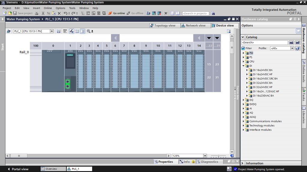
First of all, we should open up the TIA Portal and configure the required hardware including the CPU and PLC cards. You can read Part 1 to know how to do it.

Second of all, we should add the symbols to the tag table according to what I explained in Part 2.

TIA Portal Tag Table

As we have learned in Part 2, from the “Basic instructions” tab, under the “Bit logic operations” folder I drag and drop an SR Flip-Flop and assign the “Motor Contactor Coil” output or Q0.0 to that.

We have explained about Flip-Flops in Parts 2 and Part 3.

I then connect an open contact to the “Set” input of the Flip-Flop for the “Start” push button. And of course, a closed contact to the “Reset” input, for the “Stop” push button.

If you want to know why I used a closed contact for the Stop pushbutton, read this article.

Start Stop Motor PLC Program

I move on to the Network 2 to add the logic for indicator lamps. When the electric motor is not operating, the “Stop lamp” should be ON and the “Start lamp” should be OFF.

So, here I need the NO contact of the contactor and I assign its input address to this open contact.

Then, I use an Assignment (or output contact) for activating and deactivating the “Start lamp” output.

Motor Starter and Stop PLC Program

Let’s do the same thing for the “Stop lamp”. So, this time I use a closed contact but with the same address.

PLC Program Motor Control

PLC Program NO and NC Contacts VS Actual NO and NC Contacts

There is an important point here.

When the actual physical contact is open, the state of its equivalent PLC logic contacts is like this.

NO and NC in PLC Programming

And when it gets closed, its input to the PLC card (which is I0.0, for example) gets active and their state will be updated like this.

So do not confuse the open and closed contacts of the PLC logic with the actual NO and NC contacts.

Normally Open Contact in PLC

Now, let’s do a quick simulation and discuss another important practical point after that.

Simulating the Motor Start and Stop PLC Program

First of all, we should save and compile the project.

If there was no errors or warnings, we can continue to the next step.

Save and Compile the PLC Program in TIA Portal

Since in Part 3, we covered the procedure to make the software ready for simulation in TIA Portal, let’s escape this step.

As I explained, the “Stop Pushbutton” has a built-in normally closed contact and in the normal condition, when it’s not pushed, it sends a 24-volt DC signal to the PLC’s input card.

So, I simulate its input to one.

Startstop Motor Control PLC Ladder Program Simulation

The Start green lamp is OFF and the Stop red lamp is ON and that’s OK.

Let’s start the electric motor by pushing the Start pushbutton. By doing so, the motor starts working.

How to Start a Motor Using PLC

I force the input from the NO auxiliary contact which is I0.2 to True as well. Therefore, the Start lamp turns ON.

Contactor Auxiliary Contact in PLC Program

If I push the Stop pushbutton, the motor stops working.

Motor Starter and Stop PLC

I also should change the state of the NO auxiliary contact to False to change the state of the indicator lamps.

It was quite simple, right?

PLC Program to Start a Motor

NOTE: For activating and deactivating the lamps, we could also use the contactor’s coil output (Q0.0).

But as you may have guessed it’s not according to the actual situation in the plant where we have to check the functionality of the contactor in our PLC program to see if the electricity is really flowing toward the electric motor via the contactor or not.

PLC Program Motor

Proximity Sensors in Motor Rotation Monitoring

In addition to the contactor functionality check, sometimes where it’s possible, we should use a proximity sensor on the shaft of the motor to make sure if the motor is really running and it’s not stocked by any means.

Proximity Sensor in motor rotational speed measurement

In this way, as long as the proximity sensor’s input to the PLC card is getting ON/OFF with a certain frequency, we are sure that the motor is working.

Proximity Sensor in motor rotation monitoring

Electrical Schematic VS Wiring Diagram

As the last point, one of the important automation documents or drawings that is used frequently during commissioning and troubleshooting of processes is the “Control Panel Wiring Diagram” in which we can find the power and control sections of the process.

Wiring Diagram vs Schematic Diagram

But the schematic that we checked together actually does not really count as a wiring diagram, but it’s a simple schematic drawing for better understanding the concepts.

If you want to learn to read and understand an actual wiring diagram of a real control panel you can read this article.

Electrical Schematic Diagram vs Wiring Diagram

Thanks for reading another article. Please spread the word by sharing this article:

Our YouTube Channel

Contact Us

Have a question or suggestion?

[email protected]

Youtube channel

PLC Programming Course (P2): Ladder Logic PLC Programming (A Very SIMPLE Practical Example)

PLC Programming Course (P2): Ladder Logic PLC Programming (A Very SIMPLE Practical Example)

PLC Programming Course (P2): Ladder Logic PLC Programming of a Water Pumping System

In this article (Part 2), you’ll learn the correct steps to a neat and clean Ladder Logic PLC Programming of a simple process.


Ladder Logic PLC Programming is the most popular and easy to learn methods of automating our process using the PLCs. Ladder Logic or LD for short is developed under the open international standard IEC61131 for Programmable Logic Controllers.

In this part of the course, you are going to learn how to interpret the logic of the process and write a Ladder Logic program according to that.

In Part 1 of this series, we configured our PLC hardware in TIA Portal Version 15.1, and in this article (Part 2), we are going to write a PLC program in Ladder Logic (LAD) for this simple Water Pumping System and in Part 3 of this example, we’ll test it using the PLC simulator.

Logic Oriented Documents

First of all, we have to know what the logic behind our process is.

In the actual projects, there are some documents for this purpose, such as Philosophy of operation, I/O lists, Piping and Instrumentation Diagrams, Internal wiring diagrams and so on.

You’ll learn about the Control and Instrumentation documents, and drawings and how to design and draw them in software such as EPLAN or AutoCAD electrical in future articles.

I&C Documents

Understand the Logic, Before PLC Programming!

In this process, the pump should transfer the water from a “Pool” to a “Tank”, automatically.

For being automatic, there should be a “Low-Level Switch” on the bottom and a “High-Level Switch” on Top of the tank as well as a “Low-Level Switch” in the pool.

Level Switches of the Water Pumping System

1. What does Tank’s Low-Level Switch do?

As soon as the Low-Level Switch on the tank does not sense the water, PLC should send a start command to the pump and the pump will start working until the High-Level Switch senses the water.

Understanding the Process Function Before PLC Programming_Low Level Switch

2. What does Tank’s High-Level Switch do?

When the High-Level Switch senses the water, the PLC will send a stop command to the pump and the pump will shut down and will remain shut down until the Low-Level Switch of the tank does not sense the water again.

This procedure will be repeated again and again.

Understanding the Process Function Before PLC Programming_High Level Switch

3. What does Pool’s Low-Level Switch do?

There is also one other situation that PLC will shut down the pump.

This would be when there is no water in the pool and its Low-Level Switch does not sense any water.

Understanding the Process Function Before PLC Programming_Low Level Switch of the Pool

How Many Signals? How Many PLC Cards?

So, in this example, we have:

– Three inputs (which come from the level switches)

– One output (which turns ON and OFF a three-phase electric motor that drives the pump)

Therefore one Digital Input module and one Digital Output module is required.

How to Specify How Many PLC Cards We Need

Important NOTE: How to Command an Electric Motor with a PLC

We have connected the PLC output directly to the electric motor for the sake of simplicity, but as you may know, in reality, there is a contactor in between.

Since it will not affect our PLC program, let’s keep it as it is. However, we will explain the real-world PLC Control Panel devices and its wiring diagram in a future article.

How to Command an Electric Motor By a PLC

Let’s Open Up the PLC Programming Environment

In Part 1 of this article, we have explained how to create a new project and configure the PLC hardware. Therefore, I just open that project and skip the hardware configuration step.

How to Open a Project in TIA Portal V15

In the “PLC Programming” tab, there is an Organization Block by default (OB1).

Depending on the PLC program you are writing, you may need to create other new blocks or functions that you can do that from the “Add new block” submenu.

How to Add a Function Block to a PLC Program

I double-click over the “Main OB” or OB1 to open it.

OB1 is the Main Organization Block or primary environment for PLC programming.

OB1 or Main Organization Block of the PLC Programming

How to and Why We Should Add Tags to the PLC Inputs and Outputs

Before writing anything within the OB1 environment, we should add the Inputs and Outputs of the project and their addresses in a “Tag Table”.

You can create a Tag Table, in “Project tree”, on the left side of the window, and under the “PLC Tags” Folder.

How to Add PLC Tags in TIA Portal

NOTE:

As you’ll see, Tags are some kind of names that we assign to each input and output signal and they will help us to know the corresponding equipment (i. e. instrument switches, contactors, relays, etc.) of each input and output of the PLC cards. As a result, the PLC programming will be more easy.

Furthermore, we’ll have a neat and clean program afterwards so that the automation maintenance engineers can follow the PLC program and troubleshoot the process easily.

I’ll create a new tag table and name it as “Water Pumping System”. I then open it up by double-clicking on it.

How to Create PLC Tag Table in TIA Portal

The first input is the “Pool Low-Level Switch”.

After entering the name, the software automatically assigns the I0.0 address to this input which is the first channel of our only DI Card.

Adding Tags to the PLC Tag Table-PLC Programming

The next one is the “Tank Low-Level Switch” with the address of I0.1.

And the last input signal is “Tank High-Level Switch” with the address of I0.2.

Finally, as you may guess, there is our only output which I’ll name it “Motor-Pump”. And assign the address of Q0.0 to that.

Again by defining these tags in the tag table, we’ll prevent confusion when we’re writing the PLC program or during the maintenance and troubleshooting. Particularly when our process includes thousands of Inputs and Outputs.

I close the tag table to start programming.

PLC Tag Table in TIA Portal

Ladder Logic PLC Programming!

On the right-hand side of the PLC programming window (OB1), under the “Basic instructions” tab, I’ll expand the “Bit Logic Operations” folder and add an SR Flip-Flop from there by dragging and dropping it to the Network 1.

I then assign the “Motor-Pump” or Q0.0 to that.

Using an SR Flip Flop in the Ladder Logic PLC Programming

Q: Why do I chose SR Flip Flop over the RS Flip-Flop?

A: Choosing between the SR and RS Flip Flops is the matter of priority between Setting and Resetting the Flip-Flop. Meaning that, if you want your “Set” input has priority over the “Reset” input, then you should choose the RS Flip-Flop and vice versa.

I’m sure that you will understand it better after we simulate this program in Part 3 of this series.

Difference between RS and SR Flip Flops

Again, for keeping the logic as simple as possible, I assume that all of the level switches are Normally Open switches and will send a True signal (24-volt DC signal) when they sense the water and they send a False (zero signal) when they do not.

To learn more about the Normally Open sensors and Normally Closed sensors and the real cases in the industry, you may want to read this article.

Normally Open Low Level Switch

As we have learned previously, the only condition required for starting the pump is losing the Tank’s Low-Level Switch or I0.1.

Motor Start Ladder Logic PLC Program

So, I connect a closed contact to the “Set” input of the SR Flip-Flop and will assign the I0.1 to that.

Set Input of an SR Flip Flop

This way, when the I0.1 is False,then the Set input of the Flip-Flop would be one or True and consequently, the pump will turn on.

SR Flip Flop in Ladder Logic

As the next step, I click the “Reset” input of the Flip-Flop and connect an open contact to that, for the I0.2.

SR Flip Flop in PLC Program

To continue, I use an“Open Branch” and add a closed contact for I0.0.

Therefore, The electric motor will be shut down, whenever the water level reaches the low level in the Pool OR the high level in the tank.

Water Pumping System Ladder Logic PLC Program

That’s it for this part. I save the project and in Part 3, You’ll learn how to test this PLC program using the PLCSIM software and see how it works.

Thanks for reading another article. Please spread the word by sharing this article:

If you’ve missed the previous part, here is the link to that:

Part 1: How to Configure the PLC Hardware

Part 3: How to Simulate the PLC Program

Our YouTube Channel

Contact Us

Have a question or suggestion?

[email protected]

Youtube channel

PLC Programming Course (P1): PLC Hardware Configuration

PLC Programming Course (P1): PLC Hardware Configuration

PLC Programming Course (P1):

PLC Hardware Configuration

In Part 1 of this Siemens PLC Programming Course you’ll create a new project and configure the Hardware Configuration in TIA Portal.


PLC programming starts by getting familiar and comfortable with the programming environment. So first things first! In this very first article of this course, we’ll create a new project and then configure the required hardware of the PLC in the Siemens brand new software, TIA Portal or Totally integrated Automation Portal V15.1.

In Part 2 we’ll continue with PLC programming of our process and in Part 3 we’ll end up with our PLC software simulation.

Of course, this free training course will be continued with other examples of real-world processes and we believe that you’ll learn many useful practical tips and tricks in them.

Creating a New Project in TIA Portal

Totally integrated Automation Portal or TIA Portal is the Siemens brand new software that you can program your S7-1200 and S7-1500 series PLCs using that.

A project in TIA Portal contains all the hardware, network, programming, and monitoring system information.

TIA Portal V15.1

By double-clicking on the TIA Portal icon we can open up the software; after a few seconds, we see this window. From the Start menu, we obviously should choose the “Create new project”.

I name the new project as “Water Pumping System” and specify a location to save that. Then, I click “Create”. Creating a new project was pretty easy, right?

How to Create a Project in TIA Portal

Now, other submenus of the “Start” menu are enabled and you see them on the left and right hand side of the window.

Hardware Configuration in PLC Programming

As the next step that is configuring the PLC hardware, we can select either

– the “Configure a device” sub-menu or

– the “Write PLC program” sub-menu

As they both do pretty much the same thing. They both let us select the hardware and configure them before we start writing the PLC program.

I prefer choosing the “Configure a device” submenu and then click on “Add new device” to add my PLC CPU.

PLC Hardware Configuration in TIA Portal

In the “Add new device” window, in addition to Controllers (or PLCs), you see also HMI and PC Systems that we will talk about them in future articles.

Add New Device to Your Project in TIA Portal

Now, let’s select our PLC CPU. I’m going to choose an S7-1500 series PLC CPU, so I expand its folder and I think a 1513-1PN CPU is enough for our process.

When you click on each CPU, you see a technical description of that and its specific article number.

Adding a PLC to TIA Portal Project

Important NOTE:

Remember that if you are going to program an actual PLC in a plant, the process to configure the hardware requires some information beforehand.

For example, you should exactly match the Order Number or Article Number of the hardware in TIA Portal with the exact order number of your existing actual hardware. Otherwise, you will face some unwanted errors and you may not connect to your PLC.

PLC Hardware and Software Compatibility

Among the CPUs under the 1513-1 PN folder, I choose the this one (6ES7 513-1AL02-0AB0) and click “Add” to continue.

Siemens 1513-1PN PLC CPU

In the opening window, we have three tabs;

– Device view

– Network view

– Topology view

What we deal with in this article is the “Device view” tab.

As you see, the software automatically has added the appropriate Rail for the PLC and mounted the PLC on that. Something that does not happen in the older versions of Step7 software like version 5.6 or older.

TIA Portal Hardware Configuration Window

On the right-hand side of this window, there is the Hardware catalog pane in which we can find any hardware modules we need and add them to our configuration.

SIMATIC MANAGER Hardware Catalog Pane

In the next part of this example, we’ll write the PLC Program of a Water Pumping Process.

So, according to the process we need only a Digital Input (DI) and a Digital Output (DO) card as we have three discrete inputs and just one discrete output.

Estimating the Required PLC Cards

In the Hardware Catalog pane, under the DI folder, as you see there are 16 and 32-input channel cards that we can choose among them.

32 Channels Digital Input Cards

I choose a 16-channel Digital Input module (6ES7 521-1BH10-0AA0)

When I click over each module, in this case, the Digital input card, it shows us on which slots I can add this module by illustrating some blue rectangles around them.

How to Add a Digital Input Card to the Rack in TIA Portal V15

And if I expand the slots, you see that I can add it anywhere after the CPU.

I drag and drop it into the slot number 2, right after the CPU.

To Which Slot Should I Add a DI Card

As another example, if I select a Power supply module (PS module), there is another option to place that, and it is right before the CPU, in slot zero, which is a more common practice.

Adding a Power Supply Module to Slot Zero

I also need a Digital Output card and I can find it under the DQ folder. I choose a 16-channel DO or DQ card (6ES7 522-1BH10-0AA0) and add it to slot number 3 by dragging and dropping it.

Adding a Digital Output Card to the PLC Rail

I save the project and then compile it. For compiling the hardware, we should first select the rail and then the compile icon will be activated.

Save and Compile the PLC Hardware Configuration in TIA Portal

I think now we are done with PLC hardware configuration and ready to program our PLC in the next part.

Thanks for reading another article. Please spread the word by sharing this article:

Following are the links to the next parts of this PLC programming example:

Part 2: Ladder Logic PLC Programming of a Water Pumping System

Part 3: How to Simulate the PLC Program

Our YouTube Channel

Contact Us

Have a question or suggestion?

[email protected]

Youtube channel