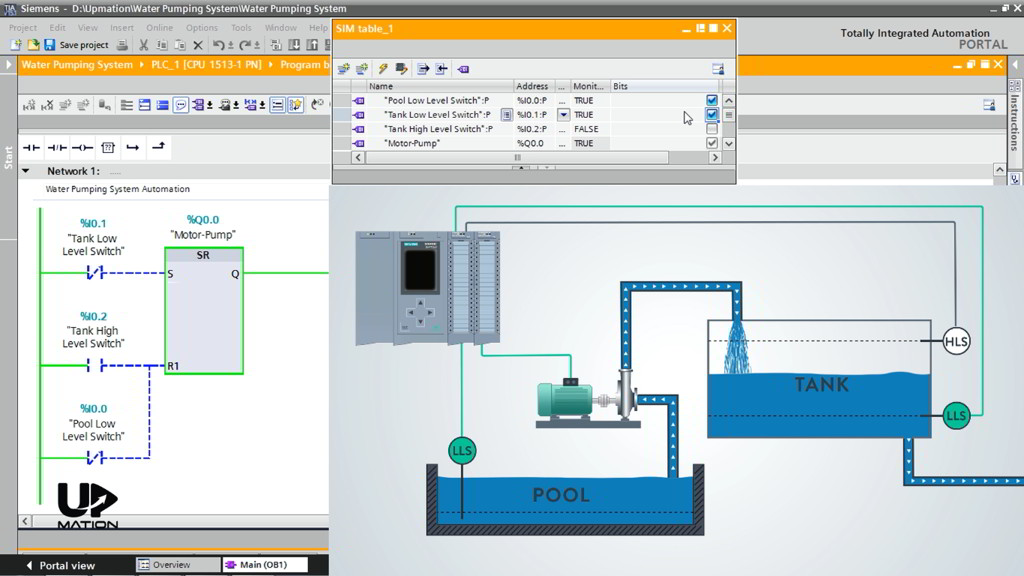
PLC Programming Course (P3): How to Simulate the PLC Program
PLC Programming Course (P3): How to Simulate the PLC Program
In this article (Part 3), you’ll learn how to simulate the PLC program that has been written in the previous part.
Simulating the PLC program is the last step before we download our program to the actual PLCs in the plant and test it with the real devices and equipment. On the other hand, it helps the beginner PLC programmers and automation engineers to gain a solid understanding of the program elements function and applications.
So, in this article, you’ll learn how to simulate the PLC program using Siemens PLCSIM software.
Part 1, was about creating a new project and PLC Hardware Configuration.
In Part 2, we wrote a Ladder Logic PLC Program for a Water Pumping System project.
How to Download the Program to PLC
Downloading to the PLC means that:
– We want to make the PLC understands that to which actual devices it is connected (Hardware and Network Configuration).
– Which commands and actions (Logic) it should take to control the process properly (PLC Program).
I’ve opened the TIA Portal and the water pumping system project and entered the Main OB environment.
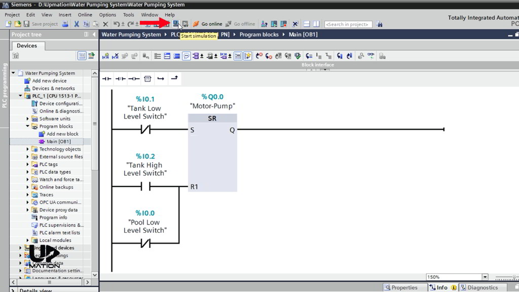
I’ll start by running the PLCSIM using the “start simulation” icon here.
NOTE: PLCSIM is the Siemens PLC Simulator that helps us to test our PLC program using a virtual PLC.
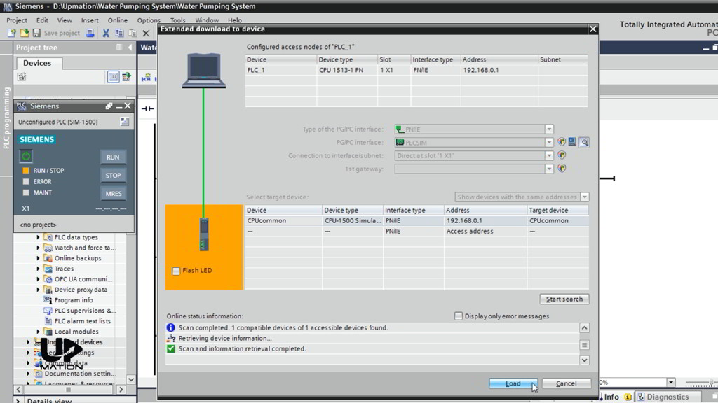
After clicking the PLCSIM icon, the virtual PLC and the “Extended download to device” window opens.
I choose the CPU and click “Load”.
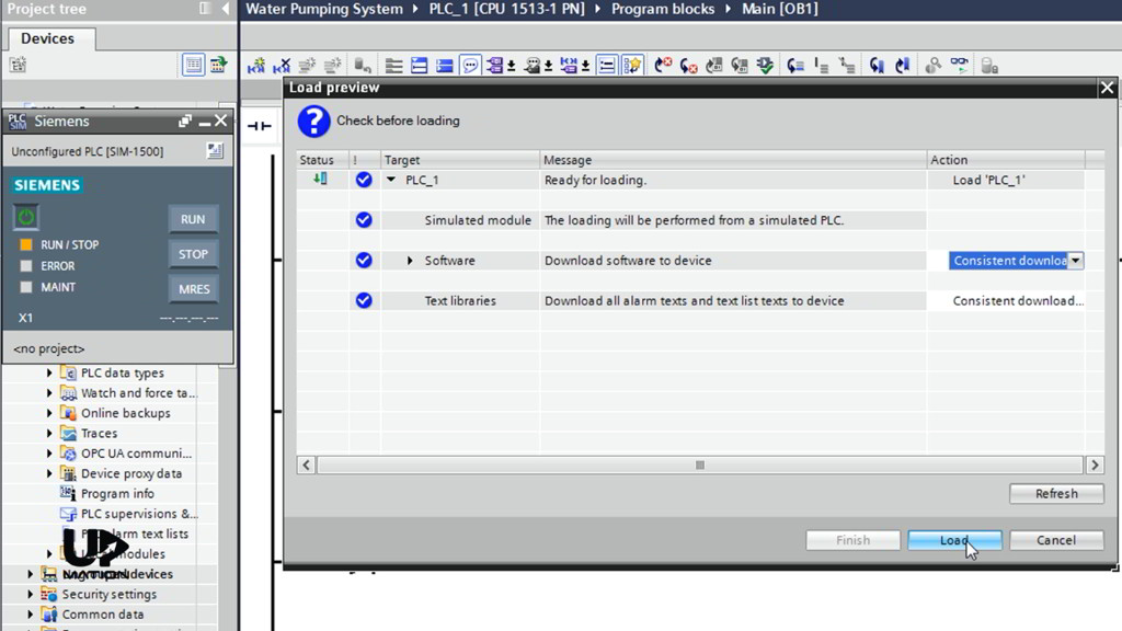
After some time the “Load preview” window opens.
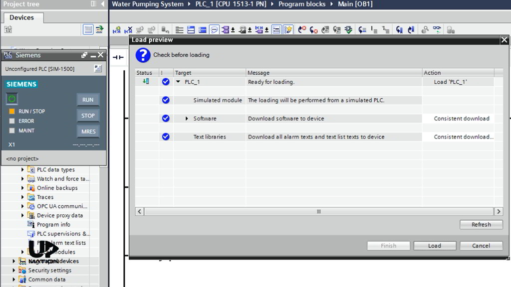
In this window, we see an action as “consistent download”.
If you have used any Functions (FC), Function Blocks (FB) or Data blocks (DB) in our software, then with consistent download you could download them automatically without any issues.
I click “Load” to download both the software and hardware to the PLC.
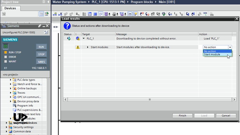
In the next window (Load results), we see that the download has been completed without any errors; besides, it asks that if we want to RUN the PLC CPU after downloading or not.
Be Careful!
In the actual processes, sometimes, if the software is not functioning properly when the PLC gets into the RUN mode right after the download, it may have some unwanted results. Because the software might start commanding some devices and runs some mechanisms.
Therefore:
1- You should test and simulate the PLC program before downloading it to the actual PLC in the plant.
2- You must think carefully, take required actions, and safety precautions before running the PLC.
I choose the “Start module” option to Run the CPU and click “Finish”.
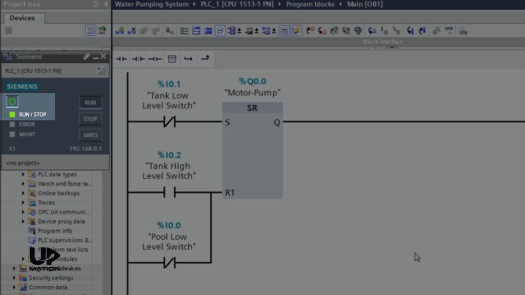
The “RUN/STOP” LED blinks and the CPU goes into the RUN mode. You could also click the “RUN” button on the CPU.
Anyways, there are some other methods for downloading the hardware and the software to the PLC.
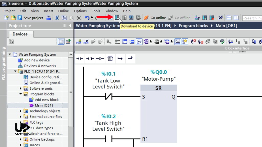
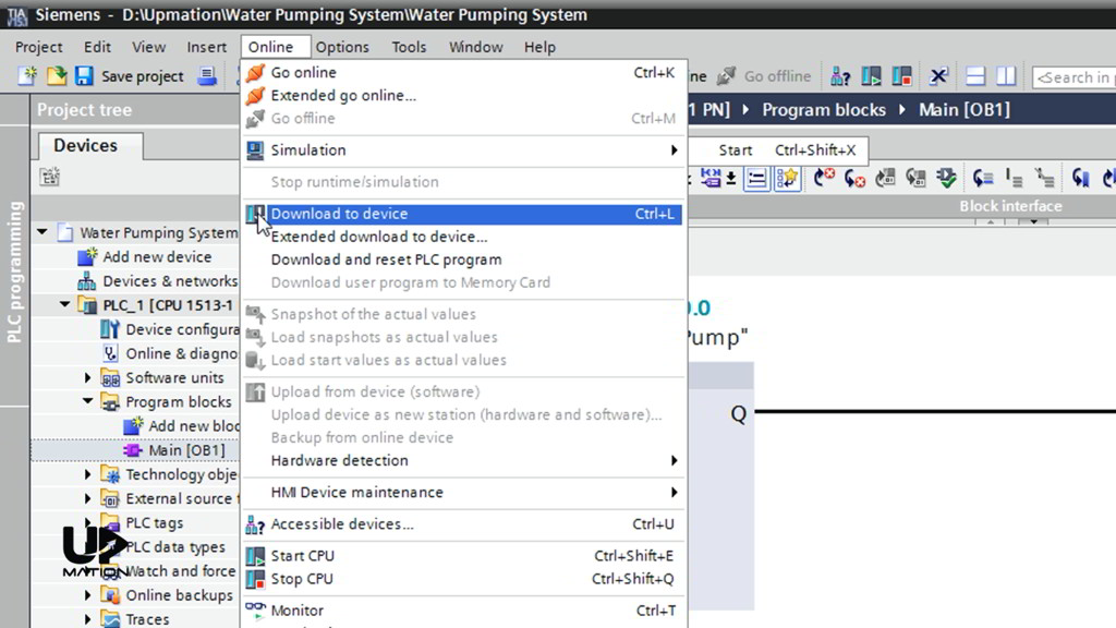
We can use the “Download to device” icon.
Or we can use the “online” menu options.
By these methods, all the software and hardware information will be downloaded to the device.
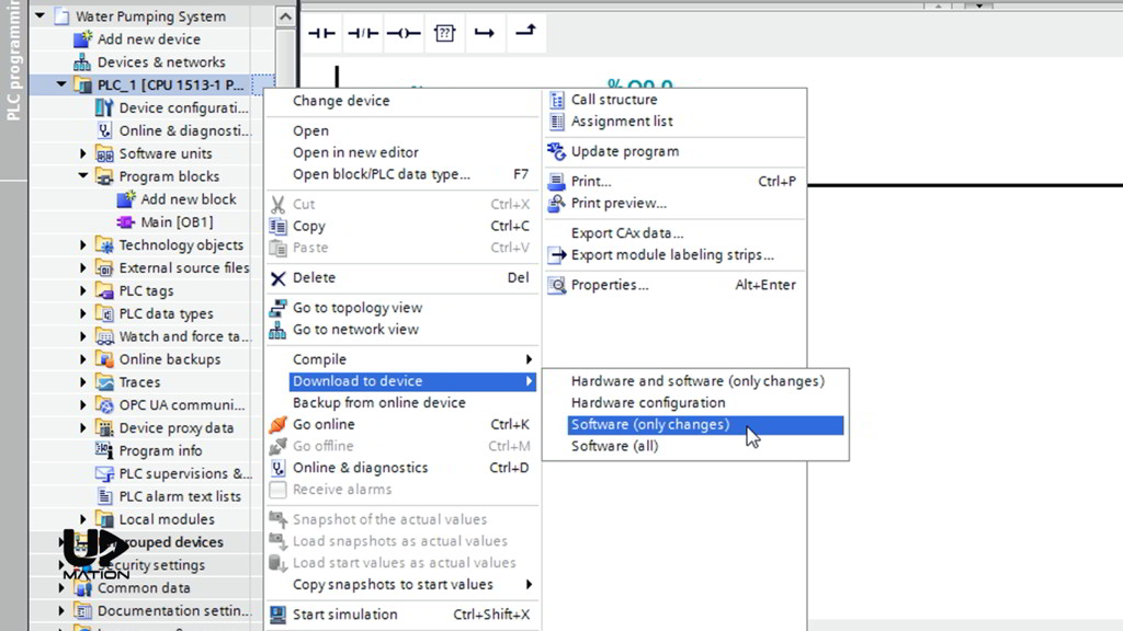
But a more common method for downloading the software or hardware to the PLC specifically when the process is running is that to simply choose the PLC and right-click on that.
In the “download to device” menu, there are four options. If you have made some changes to the software and you only want to apply those changes, you should choose “software (only changes)”.
In this way, you’ll let the CPU to stay in the RUN mode. This is especially useful when the process is running, and we don’t want to interrupt the process by stopping the CPU.
The other options will stop the CPU by the way.
So be extremely careful! When the process is running, stopping the PLC CPU abruptly may have some harmful effects on the devices, equipment, or the final product.
Monitoring the PLC Program in Real-Time
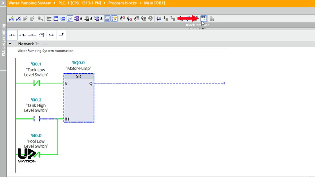
If I click the “Monitoring” Button, you see that the black lines will convert to green and blue lines that show the live or real-time condition of the level switches and the electric motor.
– Where you see the green lines it means that the condition is True.
– Where there is a blue line, the condition is False; same as the “Tank High-Level” Switch that does not sense any water, and therefore this condition is False.
Force the Input Values to Your Desired Condition (Creating the SIM Table)
To force the condition of the switches to our desired simulation condition, I have to create a table and I am going to do that via the “Switch to project view” on the PLCSIM window.
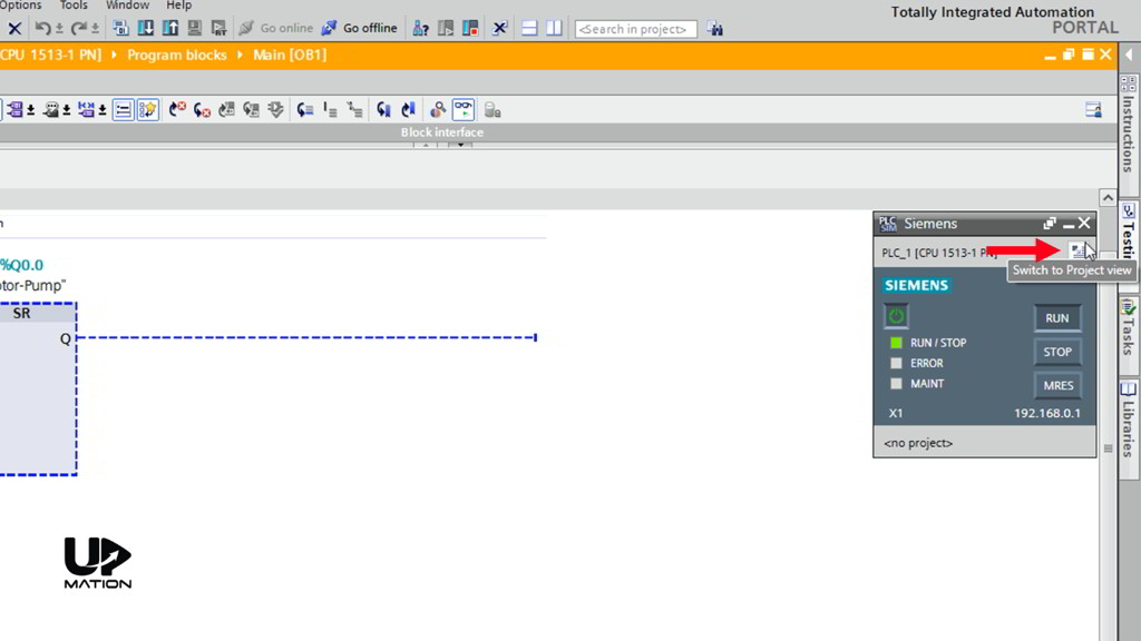
In the opening window, I create a new project and name it as “Water Pumping System”.
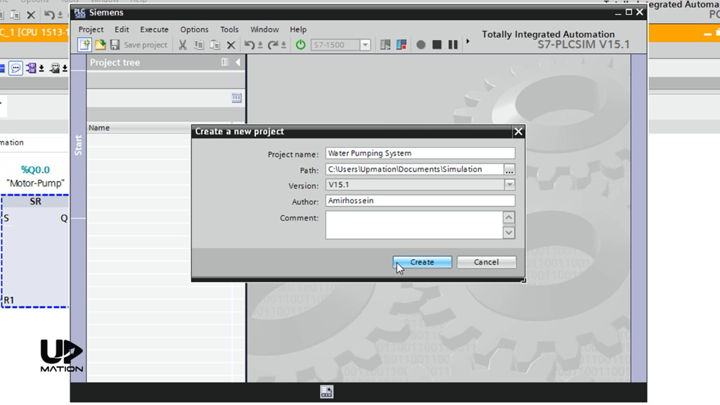
After some processing, our project has been created.
What I need is on the “project tree” and under the “SIM tables” folder. I expand it and open the SIM table 1 by double-clicking on it.
I click on the “Load project tags” icon, and it automatically loads all the project tags.
We need the “Bits” column to modify the level switches inputs to true or false.
I float this table as I want to use it for the rest of the simulation so that you can see both the Ladder Logic and the SIM table at the same time.
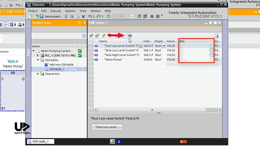
Time to Simulate the PLC Program!
Let’s start with this condition;
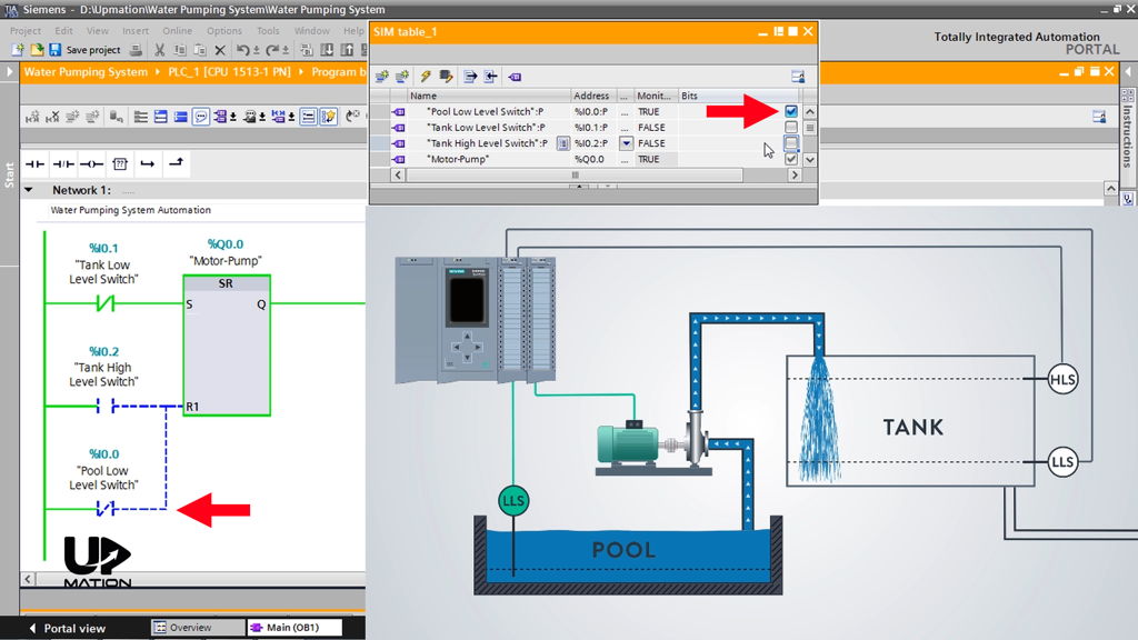
The Pool is full of water and therefore the “Pool Low-Level Switch” is active and sending a 24-volt or a TRUE signal to the PLC. Therefore, I activate its corresponding Bit in the SIM Table (Check the changes in the programming window).
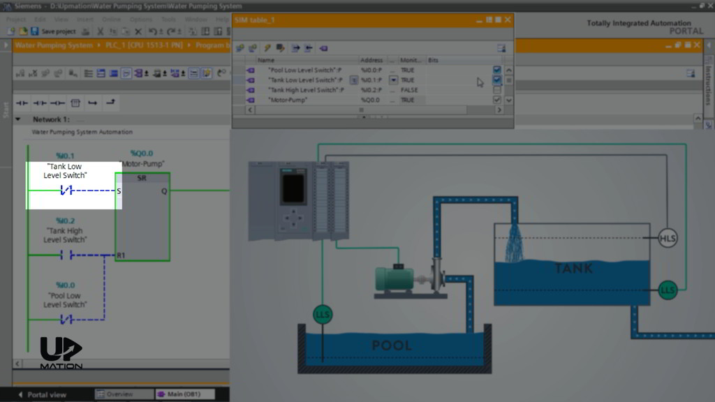
The tank is empty and both the “Tank Low-Level Switch” and “Tank High-Level Switch” are inactive and therefore the pump is working to increase the level of the water within the tank.
Very soon the “Tank Low-Level Switch” becomes active as it senses the water. To simulate its condition I activate the its Bit in the SIM Table.
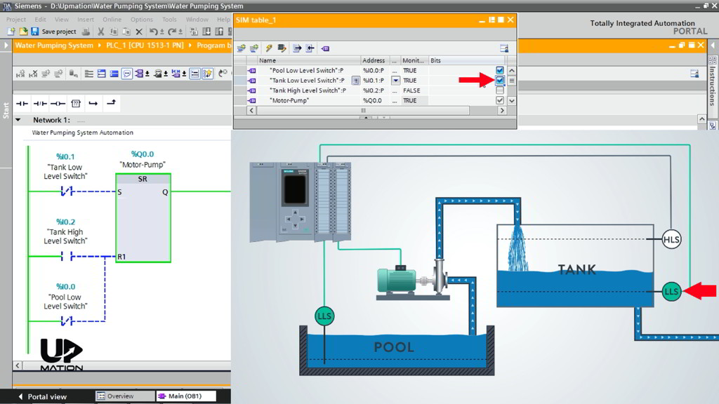
As a side note, you see that the Flip Flop keeps the “Set” command and the pump is still running despite the “Set” connection is inactive and this is how Flip-Flop works.
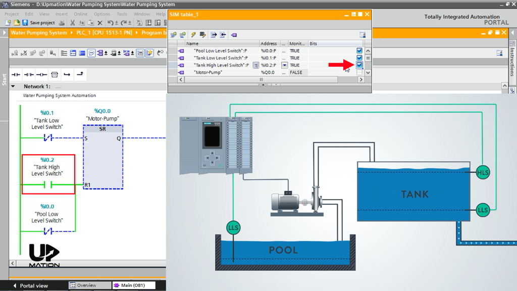
As soon as the level of the water reaches the High-Level Switch and activates that, the “Reset” input of the Flip-Flop becomes activated and therefore the pump stops working.
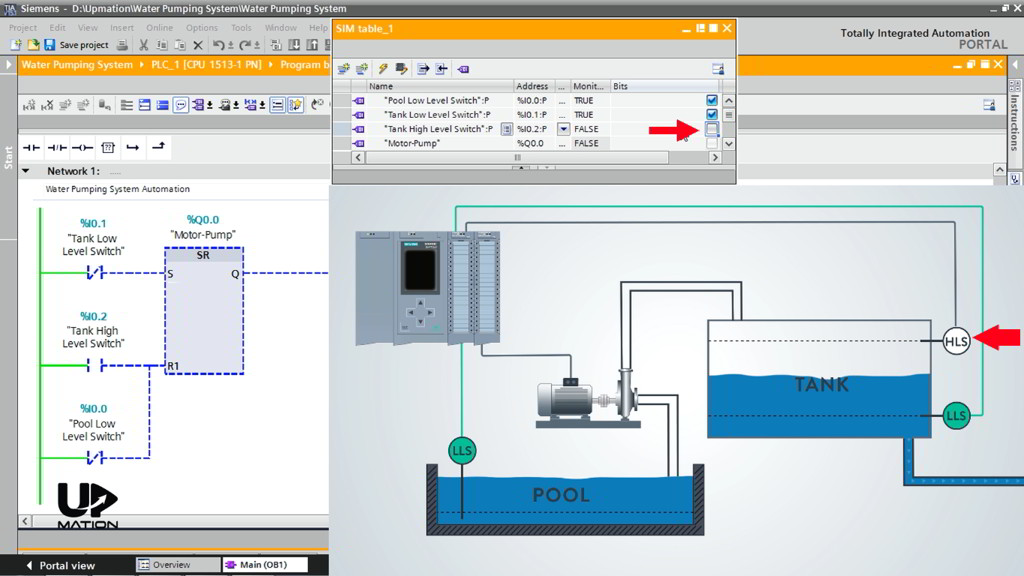
Now the water level will settle down due to the consumption through the outlet and again the “Tank High-Level Switch” becomes inactive after some time.
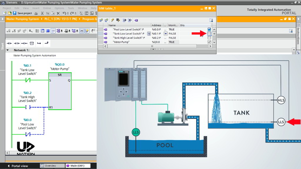
When the water reaches below the Low-Level Switch of the tank, this Switch also becomes inactive and therefore the pump begins working and the water level starts to rise again.
This scenario will be continued unless the water level in the Pool decreases and the “Low-Level Switch” of the Pool becomes inactive as a result.
In this situation, the pump stops working instantly, even if the “Set” input of the Flip-Flop is active.
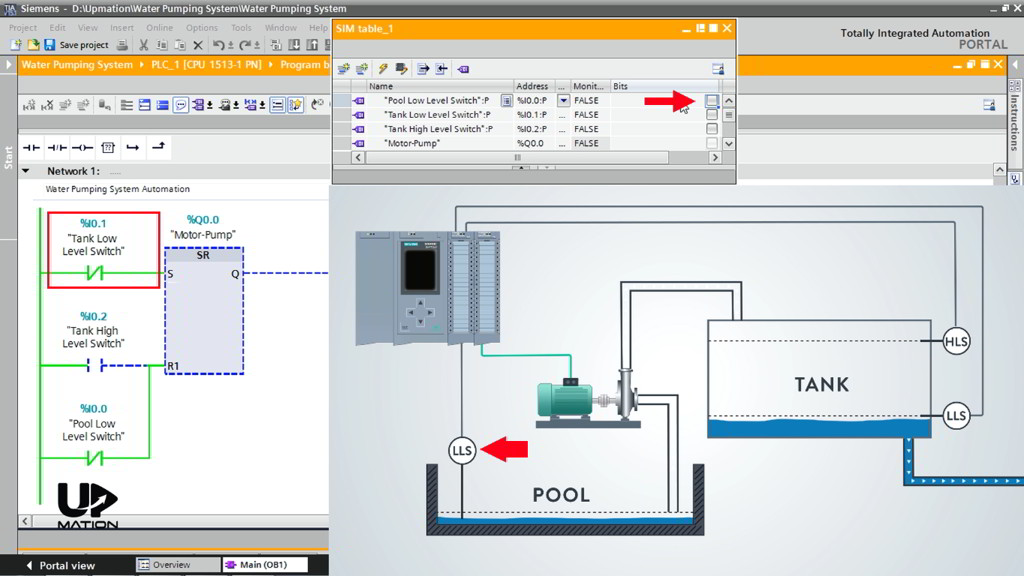
This is due to the priority of the “Reset” input in the SR Flip-Flop as we have talked about it in Part 2.
Here is why we chose the SR Flip-Flop instead of RS Flip Flop.

OK, that was all the possible conditions with this simple process. We hope you have learned something new from this article.
Thanks for reading another article. Please spread the word by sharing this article: