PLC Programming Course (P1): PLC Hardware Configuration
PLC Programming Course (P1):
PLC Hardware Configuration
In Part 1 of this Siemens PLC Programming Course you’ll create a new project and configure the Hardware Configuration in TIA Portal.
PLC programming starts by getting familiar and comfortable with the programming environment. So first things first! In this very first article of this course, we’ll create a new project and then configure the required hardware of the PLC in the Siemens brand new software, TIA Portal or Totally integrated Automation Portal V15.1.
In Part 2 we’ll continue with PLC programming of our process and in Part 3 we’ll end up with our PLC software simulation.
Of course, this free training course will be continued with other examples of real-world processes and we believe that you’ll learn many useful practical tips and tricks in them.
Creating a New Project in TIA Portal
Totally integrated Automation Portal or TIA Portal is the Siemens brand new software that you can program your S7-1200 and S7-1500 series PLCs using that.
A project in TIA Portal contains all the hardware, network, programming, and monitoring system information.

By double-clicking on the TIA Portal icon we can open up the software; after a few seconds, we see this window. From the Start menu, we obviously should choose the “Create new project”.
I name the new project as “Water Pumping System” and specify a location to save that. Then, I click “Create”. Creating a new project was pretty easy, right?

Now, other submenus of the “Start” menu are enabled and you see them on the left and right hand side of the window.
Hardware Configuration in PLC Programming
As the next step that is configuring the PLC hardware, we can select either
– the “Configure a device” sub-menu or
– the “Write PLC program” sub-menu
As they both do pretty much the same thing. They both let us select the hardware and configure them before we start writing the PLC program.
I prefer choosing the “Configure a device” submenu and then click on “Add new device” to add my PLC CPU.

In the “Add new device” window, in addition to Controllers (or PLCs), you see also HMI and PC Systems that we will talk about them in future articles.

Now, let’s select our PLC CPU. I’m going to choose an S7-1500 series PLC CPU, so I expand its folder and I think a 1513-1PN CPU is enough for our process.
When you click on each CPU, you see a technical description of that and its specific article number.

Important NOTE:
Remember that if you are going to program an actual PLC in a plant, the process to configure the hardware requires some information beforehand.
For example, you should exactly match the Order Number or Article Number of the hardware in TIA Portal with the exact order number of your existing actual hardware. Otherwise, you will face some unwanted errors and you may not connect to your PLC.

Among the CPUs under the 1513-1 PN folder, I choose the this one (6ES7 513-1AL02-0AB0) and click “Add” to continue.

In the opening window, we have three tabs;
– Device view
– Network view
– Topology view
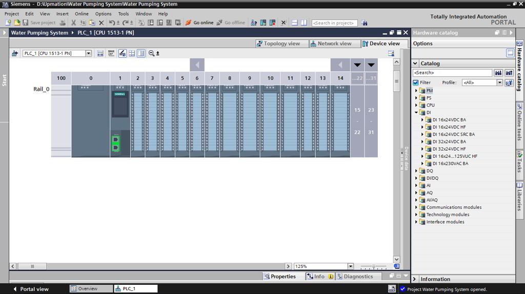
What we deal with in this article is the “Device view” tab.
As you see, the software automatically has added the appropriate Rail for the PLC and mounted the PLC on that. Something that does not happen in the older versions of Step7 software like version 5.6 or older.

On the right-hand side of this window, there is the Hardware catalog pane in which we can find any hardware modules we need and add them to our configuration.

In the next part of this example, we’ll write the PLC Program of a Water Pumping Process.
So, according to the process we need only a Digital Input (DI) and a Digital Output (DO) card as we have three discrete inputs and just one discrete output.

In the Hardware Catalog pane, under the DI folder, as you see there are 16 and 32-input channel cards that we can choose among them.

I choose a 16-channel Digital Input module (6ES7 521-1BH10-0AA0)
When I click over each module, in this case, the Digital input card, it shows us on which slots I can add this module by illustrating some blue rectangles around them.

And if I expand the slots, you see that I can add it anywhere after the CPU.
I drag and drop it into the slot number 2, right after the CPU.

As another example, if I select a Power supply module (PS module), there is another option to place that, and it is right before the CPU, in slot zero, which is a more common practice.

I also need a Digital Output card and I can find it under the DQ folder. I choose a 16-channel DO or DQ card (6ES7 522-1BH10-0AA0) and add it to slot number 3 by dragging and dropping it.

I save the project and then compile it. For compiling the hardware, we should first select the rail and then the compile icon will be activated.

I think now we are done with PLC hardware configuration and ready to program our PLC in the next part.
Thanks for reading another article. Please spread the word by sharing this article: