PLC vs DCS | Differences Between PLC and DCS

PLC vs DCS | Differences Between PLC and DCS

What are the differences between PLC and DCS?

In this article, you’ll learn about the most important differences between Distributed Control Systems (DCS) and PLC.

What is the difference between PLC and DCS? In this article, we will investigate the more important aspects of this question.

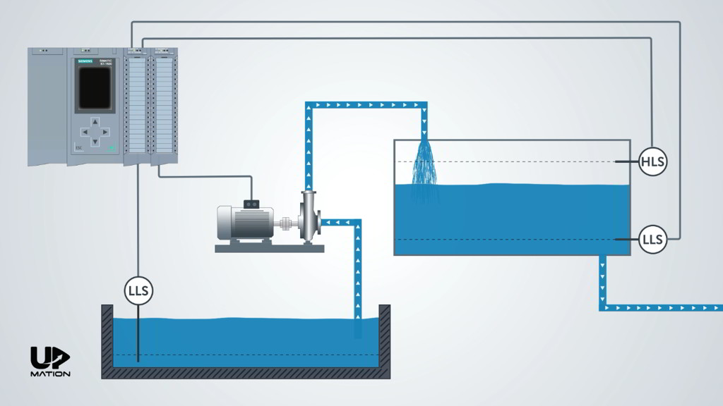
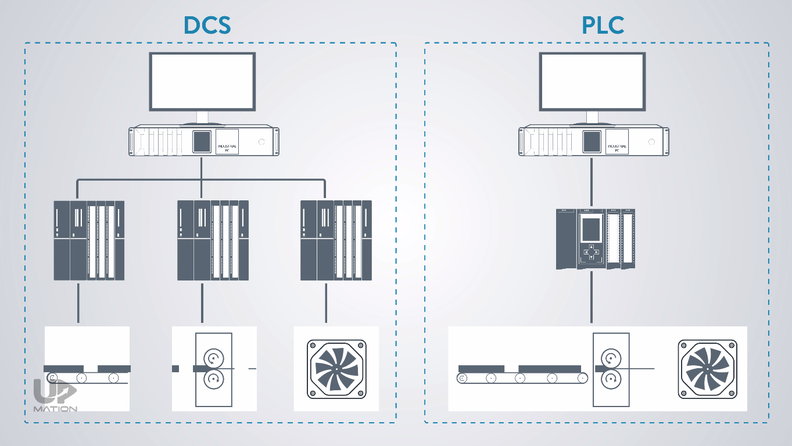
PLC and DCS in the First Look!

The DCS as its name says is a Decentralized Control System or in other words is a control method in which we have some independent CPUs.

Each CPU is in charge of controlling individual parts of the process so that if one fails, the other CPUs will continue performing their function without interruption.

PLC and DCS Differences

On the other hand, what we see in PLC control systems is like PLC mostly used for centralized control, meaning that a single PLC will control the whole process.

DCS vs PLC

But this was not the whole story! Let’s see what else is important in terms of PLC and DCS comparison.

Did PLCs Come to Replace the DCS?

The primary goal of the PLCs invention was to replace them with the old control systems which were entirely made of relays and contactors or digital signals in other words.

Old Relay Rooms

DCS or Distributed Control System was made a few years later not to replace the PLCs but to satisfy other needs in the automation industry.

Therefore, PLC and DCS have coexisted in the industry for many years in different applications and they have their significant pros and cons.

PLC vs DCS (Processes Automation)

In which processes we should use PLCs

Although the PLCs became more advanced and sophisticated these days and are even able to control the PID loops and analog signals, they are more appropriate to be used for Discrete Processes automation such as the automobile assembly line in which there are lots of digital signals and a few analog signals.

In which processes we should use DCS

DCS is more applicable for Continuous Processes with lots of analog signals and complicated PID control loops such as processes in a power plant or a refinery.

Where should we use DCS and PLC together?

In Batch or hybrid processes automation like some steel-producing industries in which we have to use DCS and PLC together, there would be some overlaps in their functions.

PLC in Process Automation

Meaning that in Batch processes we may use the PLCs to process:

– A limited number of analog signals and PID loops

– Digital or discrete signals

PLC and DCS Signals

Consider that as the number of control loops and analog signals assigned to a PLC increases, the control reliability of the process decreases dramatically.

Because if the PLC fails, then all the loops assigned to that will be out of control and the process fails consequently.

PLC Analog and Digital Signals

On the other hand, if we use the DCS to process discrete signals, since the reaction time (or Scan Cycle time) of the DCS is fairly high in comparison with the PLC, the real-time controlling of the process would not be possible.

DCS Digital and Analog Signals

PLC vs DCS (Response Time)

The scan cycle time of the DCS is more than the PLC.

This high reaction time of the DCS is due to its heavy processing duties such as processing its high-level programming languages.

DCS and PLC Scan Cycle Time

PLC vs DCS (Programming Languages)

Distributed Control Systems use high-level programming languages such as CFC or “Continuous Function Chart”.

CFC Programming Language

Continuous Function Chart (CFC) issues some extended and very useful programming, monitoring, and engineering facilities like lots of predefined functions.

DCS Programming Languages

These high-level languages will generate lots of codes after getting compiled and puts a lot of burden on the CPU.

As a result, the response of the system to the important inputs will not be fast enough.

On the contrary, the popular Low-Level PLC programming languages such as Ladder logic, Function Block Diagram, and particularly STL or Structured Text Language, are closer to the machine language

PLC Programming Languages

therefore the generated codes are remarkably fewer than the DCS programming languages. It is the reason that the PLC is used for the emergency systems.

PLC vs DCS

PLC vs DCS (Hardware)

So, to take advantage of the languages like CFC, the hardware of the DCS should be more powerful than a PLC system.

However, with today’s advancements in technology, the hardware of the DCS and PLC are more closed to each other.

PLC vs DCS Hardware

Sometimes it is not possible to judge whether a control system is DCS or PLC only by looking at its electrical control panel.

Even in some cases, PLC control systems use the same CPU as the ones commonly used in Decentralized Control Systems.

PLC vs DCS (Monitoring Systems)

In DCS, there is an integrated software package in which there is a fairly complete set of monitoring facilities.

In PLC systems, however, usually, there is no relationship between the programming and the monitoring environments, and they need their own time to be created and developed.

PLC and DCS Monitoring Systems

In DCS, by calling the control functions into the programming environment, their corresponding graphical objects will automatically be added to the HMI pages with their addresses. In this way, we’ll save some precious time!

Siemens PCS7

PLC vs DCS (Reliability)

the Decentralized Control Systems are more reliable in comparison with the PLC control systems not just for being decentralized, but for being usually redundant in different levels; from CPUs and Power Supplies to Servers, network switches, and network cables.

DCS Redundancy

Final Thoughts

There are lots of benefits in using both the DCS and PLC. As the DCS response time is more than the PLC, the DCS is better to be used for processes with more analog signals and PID loops whereas the PLC systems are better for processes with more discrete and less analog signals.

In DCS we can benefit from numerous predefined functions and function blocks and its high-level programming languages but in PLCs, we often have to write and define the functions by ourselves.

You also learned about the benefits of the DCS in designing the monitoring system.

The network architecture of the DCS is way easier to implement using its integrated software and hardware package. However, DCS software and hardware packages cost a lot more than PLC equivalents.

Thanks for reading another article. We hope you have learned something new and if you liked this video please share it with your friends and colleagues:

Our YouTube Channel

Contact Us

Have a question or suggestion?

[email protected]

Youtube channel

PLC Programming Course (P2): Ladder Logic PLC Programming (A Very SIMPLE Practical Example)

PLC Programming Course (P2): Ladder Logic PLC Programming (A Very SIMPLE Practical Example)

PLC Programming Course (P2): Ladder Logic PLC Programming of a Water Pumping System

In this article (Part 2), you’ll learn the correct steps to a neat and clean Ladder Logic PLC Programming of a simple process.


Ladder Logic PLC Programming is the most popular and easy to learn methods of automating our process using the PLCs. Ladder Logic or LD for short is developed under the open international standard IEC61131 for Programmable Logic Controllers.

In this part of the course, you are going to learn how to interpret the logic of the process and write a Ladder Logic program according to that.

In Part 1 of this series, we configured our PLC hardware in TIA Portal Version 15.1, and in this article (Part 2), we are going to write a PLC program in Ladder Logic (LAD) for this simple Water Pumping System and in Part 3 of this example, we’ll test it using the PLC simulator.

Logic Oriented Documents

First of all, we have to know what the logic behind our process is.

In the actual projects, there are some documents for this purpose, such as Philosophy of operation, I/O lists, Piping and Instrumentation Diagrams, Internal wiring diagrams and so on.

You’ll learn about the Control and Instrumentation documents, and drawings and how to design and draw them in software such as EPLAN or AutoCAD electrical in future articles.

I&C Documents

Understand the Logic, Before PLC Programming!

In this process, the pump should transfer the water from a “Pool” to a “Tank”, automatically.

For being automatic, there should be a “Low-Level Switch” on the bottom and a “High-Level Switch” on Top of the tank as well as a “Low-Level Switch” in the pool.

Level Switches of the Water Pumping System

1. What does Tank’s Low-Level Switch do?

As soon as the Low-Level Switch on the tank does not sense the water, PLC should send a start command to the pump and the pump will start working until the High-Level Switch senses the water.

Understanding the Process Function Before PLC Programming_Low Level Switch

2. What does Tank’s High-Level Switch do?

When the High-Level Switch senses the water, the PLC will send a stop command to the pump and the pump will shut down and will remain shut down until the Low-Level Switch of the tank does not sense the water again.

This procedure will be repeated again and again.

Understanding the Process Function Before PLC Programming_High Level Switch

3. What does Pool’s Low-Level Switch do?

There is also one other situation that PLC will shut down the pump.

This would be when there is no water in the pool and its Low-Level Switch does not sense any water.

Understanding the Process Function Before PLC Programming_Low Level Switch of the Pool

How Many Signals? How Many PLC Cards?

So, in this example, we have:

– Three inputs (which come from the level switches)

– One output (which turns ON and OFF a three-phase electric motor that drives the pump)

Therefore one Digital Input module and one Digital Output module is required.

How to Specify How Many PLC Cards We Need

Important NOTE: How to Command an Electric Motor with a PLC

We have connected the PLC output directly to the electric motor for the sake of simplicity, but as you may know, in reality, there is a contactor in between.

Since it will not affect our PLC program, let’s keep it as it is. However, we will explain the real-world PLC Control Panel devices and its wiring diagram in a future article.

How to Command an Electric Motor By a PLC

Let’s Open Up the PLC Programming Environment

In Part 1 of this article, we have explained how to create a new project and configure the PLC hardware. Therefore, I just open that project and skip the hardware configuration step.

How to Open a Project in TIA Portal V15

In the “PLC Programming” tab, there is an Organization Block by default (OB1).

Depending on the PLC program you are writing, you may need to create other new blocks or functions that you can do that from the “Add new block” submenu.

How to Add a Function Block to a PLC Program

I double-click over the “Main OB” or OB1 to open it.

OB1 is the Main Organization Block or primary environment for PLC programming.

OB1 or Main Organization Block of the PLC Programming

How to and Why We Should Add Tags to the PLC Inputs and Outputs

Before writing anything within the OB1 environment, we should add the Inputs and Outputs of the project and their addresses in a “Tag Table”.

You can create a Tag Table, in “Project tree”, on the left side of the window, and under the “PLC Tags” Folder.

How to Add PLC Tags in TIA Portal

NOTE:

As you’ll see, Tags are some kind of names that we assign to each input and output signal and they will help us to know the corresponding equipment (i. e. instrument switches, contactors, relays, etc.) of each input and output of the PLC cards. As a result, the PLC programming will be more easy.

Furthermore, we’ll have a neat and clean program afterwards so that the automation maintenance engineers can follow the PLC program and troubleshoot the process easily.

I’ll create a new tag table and name it as “Water Pumping System”. I then open it up by double-clicking on it.

How to Create PLC Tag Table in TIA Portal

The first input is the “Pool Low-Level Switch”.

After entering the name, the software automatically assigns the I0.0 address to this input which is the first channel of our only DI Card.

Adding Tags to the PLC Tag Table-PLC Programming

The next one is the “Tank Low-Level Switch” with the address of I0.1.

And the last input signal is “Tank High-Level Switch” with the address of I0.2.

Finally, as you may guess, there is our only output which I’ll name it “Motor-Pump”. And assign the address of Q0.0 to that.

Again by defining these tags in the tag table, we’ll prevent confusion when we’re writing the PLC program or during the maintenance and troubleshooting. Particularly when our process includes thousands of Inputs and Outputs.

I close the tag table to start programming.

PLC Tag Table in TIA Portal

Ladder Logic PLC Programming!

On the right-hand side of the PLC programming window (OB1), under the “Basic instructions” tab, I’ll expand the “Bit Logic Operations” folder and add an SR Flip-Flop from there by dragging and dropping it to the Network 1.

I then assign the “Motor-Pump” or Q0.0 to that.

Using an SR Flip Flop in the Ladder Logic PLC Programming

Q: Why do I chose SR Flip Flop over the RS Flip-Flop?

A: Choosing between the SR and RS Flip Flops is the matter of priority between Setting and Resetting the Flip-Flop. Meaning that, if you want your “Set” input has priority over the “Reset” input, then you should choose the RS Flip-Flop and vice versa.

I’m sure that you will understand it better after we simulate this program in Part 3 of this series.

Difference between RS and SR Flip Flops

Again, for keeping the logic as simple as possible, I assume that all of the level switches are Normally Open switches and will send a True signal (24-volt DC signal) when they sense the water and they send a False (zero signal) when they do not.

To learn more about the Normally Open sensors and Normally Closed sensors and the real cases in the industry, you may want to read this article.

Normally Open Low Level Switch

As we have learned previously, the only condition required for starting the pump is losing the Tank’s Low-Level Switch or I0.1.

Motor Start Ladder Logic PLC Program

So, I connect a closed contact to the “Set” input of the SR Flip-Flop and will assign the I0.1 to that.

Set Input of an SR Flip Flop

This way, when the I0.1 is False,then the Set input of the Flip-Flop would be one or True and consequently, the pump will turn on.

SR Flip Flop in Ladder Logic

As the next step, I click the “Reset” input of the Flip-Flop and connect an open contact to that, for the I0.2.

SR Flip Flop in PLC Program

To continue, I use an“Open Branch” and add a closed contact for I0.0.

Therefore, The electric motor will be shut down, whenever the water level reaches the low level in the Pool OR the high level in the tank.

Water Pumping System Ladder Logic PLC Program

That’s it for this part. I save the project and in Part 3, You’ll learn how to test this PLC program using the PLCSIM software and see how it works.

Thanks for reading another article. Please spread the word by sharing this article:

If you’ve missed the previous part, here is the link to that:

Part 1: How to Configure the PLC Hardware

Part 3: How to Simulate the PLC Program

Our YouTube Channel

Contact Us

Have a question or suggestion?

[email protected]

Youtube channel