How to Read a P&ID Correctly – Part 1
How to Read P&IDs Correctly
Part 1
In this article, you’ll learn what Piping and Instrumentation Diagrams are and how to read them correctly.
After exploring lots of videos and articles about P&IDs we concluded that reading the valve symbols, lines, codes, etc. one by one and memorizing them, is the most tedious and wrong method of learning how to read P&IDs!
So in this article, we’ll begin a new series about how to design and read piping and instrumentation diagrams correctly.
Before we dig into the subject, let’s clarify some common mistakes and ambiguities, mostly among students or junior engineers.
Common Mistakes about P&IDs
1. P&ID versus PID
PID and P&ID are totally different things! PID stands for Proportional, Integral, and Derivative which are parameters used in algorithms for controlling the process loops.

2. What P&ID Stands for
You might hear different extended formats of P&ID like the followings, and all of them represent the same document.
— Piping and Instrumentation Diagram
— Process and Instrument Diagram
— Piping and Instrument Drawing

3. Number of Pages in a P&ID Document
Similar to other documents like Electrical Wiring Diagrams, P&IDs are typically more than a single page.
Four, five, ten, or more pages depending on the process size, and you only see a specific part of the process on each page. These sheets are usually interconnected with each other.

4. Relevant Documents to Piping and Instrumentation Drawings
There are relevant or maybe close documents to P&IDs that have their own usage and you should not confuse them with each other.

For instance, a Piping Isometric Drawing.
It is a sort of shop drawing that is mostly used by piping specialists, and in addition to P&ID information, they include lots of data about fabricating pipelines such as type of fittings, flanges, direction and elevation of the pipes and instruments, and other characteristics.

Where to Start Reading a P&ID
Another fundamental, yet related document that P&IDs are actually designed based on that, is PFD or Process Flow Diagram.
In a Process Function Description you mostly see the major equipment plus some pieces of piping.

In a Piping and Instrumentation Diagram we have quite a lot more information, in comparison with the Process Flow Diagram, don’t we?

You can think of a PFD as a preliminary version of a Piping and Instrumentation Diagram.
So, to avoid confusion, a good starting point to read a new P&ID is the Process Flow Diagram, if available.

Piping & Instrumentation Diagram Example
Now, let’s explore some P&ID examples.
I have elected a part of a P&ID from a chemical process and manipulated it to essentially emphasize the automation and instrumentation aspects of P&IDs.

So, you can consider it more of an Instrument Diagram than a Piping and Instrumentation Diagram!

1. Which Documents We Need to Read a P&ID
To investigate a P&ID, first, you should know that every company has its own way of illustrating and naming the symbols.
They show their symbology methods in detail, in some lead sheets called, ‘Legend and Abbreviation’ and usually it’s merely called Legend.

Inside a legend, you’ll see a lot of symbols for:
– Primary equipment
– Instrumentation
– Numbering and identification methods
– Piping arrangement
– Typical details for different instruments
and a lot more.

Although the fundamentals of these data are mainly derived from a standard document, known as ISA5.1, and its latest revision was released in 2009.
ISA5.1 is a standard document from the American National Standard Institution for Instrumentation Symbols and Identification.
You can download a pdf format of ISA5.1 from here.

So, to interpret a piping and instrumentation diagram we have two helpful documents!
1. P&ID’s Legend

All right! Let’s get back to the example.
2. P&ID Step by Step!
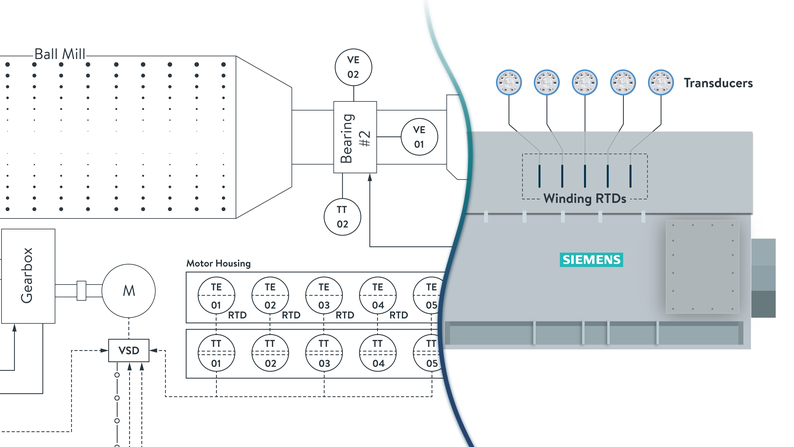
The material comes inside the Ball Mill using a screw conveyor and gets out of that in the form of powder. It has a very powerful motor and gearbox to rotate it.

There are some utility units like gearbox lubrication and grease unit as well.

In large-scale projects, normally, utilities have separate sheets of P&ID and we will refer to them using some arrows.
There are the name and the drawing number of that P&ID inside the arrow.

On page 36 of ISA5.1, we have 20 different types of graphical symbols for illustrating the instrumentation on the P&IDs and I will explain them one by one in this part and next parts of this article series.

The first and most used instrument symbol is the simple circle or bubble.
It is used for physical devices that are installed locally in the field and directly on the main equipment like the variety of sensors or transmitters.

For instance, we have two vibration sensors on bearing number 1 of the Ball Mill.
To identify that it is a vibration sensor I put the letters VE inside the circle.

These letters are corresponding to page 30 of the standard.
The first letter is ‘V’ which means ‘Vibration’ and the succeeding letter is ‘E’ which means ‘Element’ or ‘Sensor’.

We have other sensors mounted directly on different parts of the Ball Mill.
Generally, these symbols represent a physical instrument or device – and not a computer-based or HMI object.

Among the P&ID symbols we have five instrument symbols for local mounted devices.
If the physical instrument is visible and accessible to us, we use solid lines inside the circles and if they are not accessible, we will use dashed lines.

You might ask how a local instrument could be invisible to us.
Let me explain with an example.
You might already know that almost all electric motors have temperature sensors on their windings. As in a normal situation, these temperature sensors are inaccessible and invisible to us, we have to consider a dashed line in the middle of the circles.

You might argue that these sensors are not mounted on or inside a ‘panel’, so why would we consider a circle for them?
I would say that sometimes it depends on the designer how to interpret this symbology and if they deviate from the standard, they usually mention that in the legend, or they might write a note just beside the page and explain that.

According to page 43 of the ISA standard, we can also specify the type of sensor adjacent to its symbol.

Of course, this note refers us to table 5.2.2.
If we look at that table, under the temperature section, we can see the abbreviation for different sorts of temperature elements, including RTD for Resistance Temperature Detector.

So we can put an RTD beside the temperature element symbols, inside the P&ID.

These RTD sensors could be directly connected to the PLC cards, but in this case, they have been connected to some transducers within a local box that stuck to the motor housing.

So, in the P&ID, for illustrating the Temperature Transducers that are located within a local box, we can use a circle with two parallel dashed lines.
")
About connecting the P&ID objects to each other, there is a specific tabular guide on page 46 of the standard.

As shown on page 46 of ISA5.1, we should use a dashed line for electronic signals or electric connections.

Thus, I connect all the sensors and their transducers, or let’s say transmitters, using a dashed line.
I will complete this P&ID in the next video with lots of crucial key points.
Until then please download the ISA5.1 using the description links and have a look at that.
As always, we hope you enjoyed this article. Please spread the word by sharing this article with your friends and colleagues.