How to Read a PLC Wiring Diagram (Control Panel Wiring Diagram)

How to Read a PLC Wiring Diagram (Control Panel Wiring Diagram)

How to Read a PLC Wiring Diagram?

In this article, you’ll learn how to read, understand and use a PLC wiring diagram.

Reading a PLC Wiring Diagram is one of the must-to-learn skills for every automation and electrical engineer. Despite different standards of these types of drawings, you’ll learn using actual industrial drawings and some PLC wiring best practices.

In Part 1 of this series, you’ve learned how to read and understand a wiring diagram of an industrial control panel and in this Part, we’re going to continue with the PLC part of that same control panel. In this article, you’ll learn about the PLC and its modules’ wiring diagram. You’ll also see how a VFD is related to a PLC in a wiring diagram.

So, if you’ve missed Part 1, you may want to read that article first and come back and continue with this part.

A Quick Review of Part 1

As we’ve mentioned in part 1, this is an actual wiring diagram of a standard control panel with more than 140 pages and we’ll check only some of the pages as the others are somehow similar.

PLC Wiring Diagram Examples

Do you remember the first rule of thumb from the previous part?

This was the reading directions! You should read this wiring diagram from left to right and from top-down just like reading a book.

PLC Wiring Diagram Reading Directions

The second important note was these column numbers and their combination with the page number to understand the addressing system of the wiring diagram.

For example, if you see a number like 36.6 beside or below a component in PLC wiring diagram, it means that it has been used in page 36, column 6.

Addressing Different Components in PLC Wiring Diagram

Let’s Start Reading PLC Wiring Diagram!

This page is the wiring diagram of our S7 300 series PLC and the operator touch panel. So, let’s start from here.

Siemens S7 300 PLC Wiring Diagram

We know that these pages are related to each other.

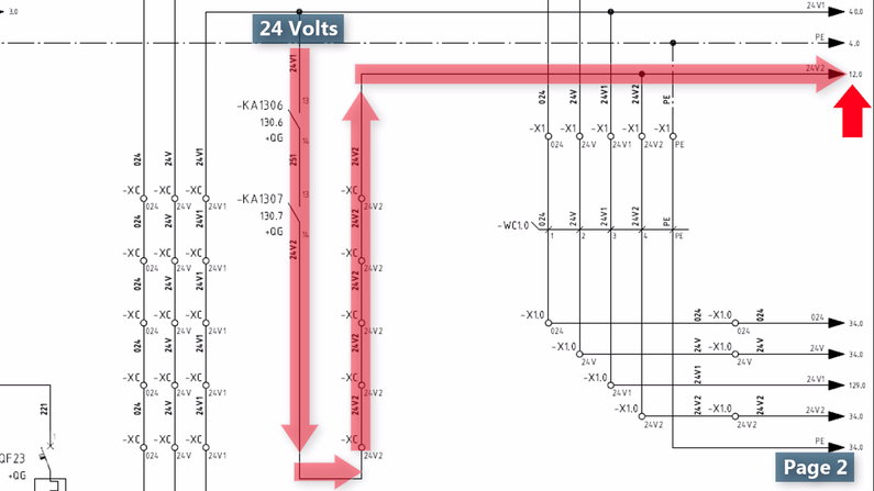
As you see our 24-volt power is coming from page 11, column 9, and page 12, column 1.

Our earth is also has been branched from page 17 column 9.

24 Volts Power Supplu in PLC Wiring Diagram

If we trace these addresses, we’ll reach page two, where we had our 24 volts power supply that we had checked in the previous article.

PLC Wiring Diagram Symbols

The 24 volts, zero volts, and the earthing are respectively connected to L+, M, and PE terminals on the PLC CPU.

Same as always, if we’re designing a PLC wiring diagram and we’re not sure about the connections of our device, we have to take a look at its datasheet or manual.

For example, here we should see the PLC datasheet to figure out where we should exactly connect the wires.

Siemens S7 PLC Power Wiring Diagram

On the other hand, the operator panel has been powered up from the X4.0 terminal blocks.

Operator Panel Wiring Diagram

How to Illustrate Cable Tags in Wiring Diagram

The power from X4.0 is being transferred using a cable with the WC4.0 tag.

This is the standard way to illustrate a cable and its core numbers in a wiring diagram.

Wire Diagram Cable Tags

The other things we observe on this page are PLC cards that are in the same rack as the CPU.

The arrow on the left hand side of the PLC rack means that the rack will be continued on the next page of the PLC wiring diagram.

PLC Wiring Diagram

Profibus Communication with PLC

You also see communication cabling here.

The operator panel is communicating to the PLC directly via the MPI port of the CPU using a Profibus cable.

Profibus PLC Siemens in Wiring Diagram

The WCDP5 cable is also a Profibus cable as it’s connected to the DP port of the CPU.

Profibus Communication in PLC Wiring Diagram

And you can read the color of the cable just beside of the cable tags. It is red with green stripes.

Cable Color in Wiring Diagram

To know where this cable is connected, we should refer to page 34 and column number zero.

Addressing Components in PLC Wiring

Using Remote I/Os to Reduce Signal Cabling

Here is our cable from page 30.

If we look carefully at this page, we understand that this is a remote IO from a brand named WAGO.

There is the Head module or Interface module with a Profibus DP connection that is connected directly to CPU.

And there are the Signal or IO modules as well.

PLC Remote IO Module in Wiring Diagram

PLC Analog Output Card Wiring Diagram

Let’s get back to page 30 to continue with our first PLC card wiring diagram.

Wiring Diagram for PLC Analogue Output Card

If you’ve been familiar with the Siemens PLC cards and modules or you simply google this order number (6ES7332-5HD01-0AB0), you’ll understand that this is an Analog output card with four channels.

6ES77332-5HD01-0AB0

In the PLC wiring diagram you see that each channel of this analog output card is dedicated to a single device.

Siemens 4 Channel Analog Output in PLC Wiring Diagram

The page number where we can find the wiring diagram for this Analog Output card is here in the middle; page 40, column zero.

how to read plc schematics

On page 40 we can see our analog output card with four channels.

PLC Wiring Schematic

In the first look, we see some connections on the card, from one to 20.

Each card has some screw connections that we should connect the wires to them. You may know them as front connectors.

These numbers are the screw numbers on the front connector of the card.

PLC Front Connector in Wiring Diagrams

Same as our PLC, we have to connect a 24-volt power to turn on our PLC card.

Power to PLC Analog Cards

If you compare it with the card’s wiring diagram within its manual, then you see that the connection number 1 and 20 are for connecting the 24-volt DC power.

This is what you see in the main wiring diagram as well.

Siemens Analog Output Module Manual

According to the manual, we’ve configured the card for the voltage output.

Then the first two channels of this card are for closer connections with no compensation for the wire resistance.

Analog Voltage Output PLC Wiring Diagram

In this case, you should jumper connections 3 and 4 and connections 5 and 6 to each other at the PLC card.

Analog Input and Output Wiring in PLC

Channels 3 and 4 should be used for 4-wire connections.

Important NOTE:

Make sure that the cable shield has been connected to the earth bar for noise reduction, particularly in the case of voltage output.

PLC Analog Output Wiring

The wiring diagram for the card will be different if we decide to use the electrical current output format.

PLC Analog Current Output Wiring

The PLC programmer can adjust the settings in the software to specify whether it would be a voltage or current type of output.

Output Types of PLC Card in TIA Portal

In the main wiring diagram, the first two channels were left empty and channels three and four have been occupied.

Analog Output Card Wiring

How a VFD is Connected to PLC in a Wiring Diagram

Normally, there should be some descriptions for each channel of the card for us to know to which device this channel is going to be connected or already has been connected.

For example, channel 3 is assigned to the “film traverse motor speed reference”;

The “film traverse” is the name of the mechanism that the electric motor is driving that. But from the “motor speed reference”, we understand that this output voltage is telling the motor to adjust its speed at each moment, according to the voltage it’s receiving.

Of course, it’s not possible without a VFD (Variable Frequency Drive) in between the motor and the PLC card.

Siemens PLC Output Voltage

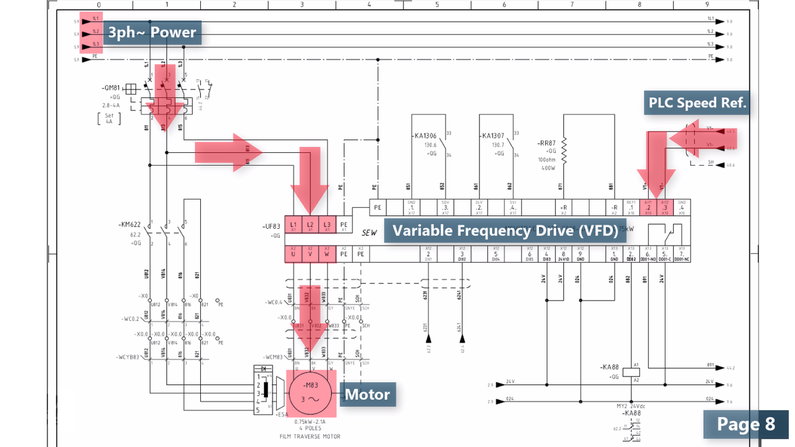
As channel three of the PLC card is connected to 8.9 (Page 8, column 9) we should turn to page 8, column 9 to see the rest of the wiring diagram.

Analog Input to VFD

On this page, we see that our speed reference output is connected to the terminals of an SEW VFD.

PLC and VFD Communication Wiring Diagram

On this page, we generally see that the AC three-phase power is connected to the inputs of the VFD.

The VFD is adjusting the power flowing toward the electric motor according to the speed reference it’s receiving from the PLC analog output card.

VFD Motor Wiring Diagram

For instance, consider that the speed reference voltage is between 0 to 10 volts and the motor nominal speed is 1500 rpm;

When the PLC card, sends out a 5-volt signal to the VFD, the VFD will adjust the power to the motor so that it will rotate with 50% of its nominal speed which is 750 rpm.

PLC VFD Control

The rest of page 8 of this PLC wiring diagram is related to some interlocks (or conditions) and also the power to the fan of the electric motor.

control panel wiring diagram

PLC Digital input Card Wiring Diagram

Now, let’s see what we have for a digital or discrete input card of the PLC.

Digital input Card Siemens

Clearly, the designer has shown the wiring diagram of this card on four different pages, which is a good idea to prevent congestion.

Let’s turn to page 43 to check the first byte of this digital input module.

plc panel wiring

As you might guess, some pushbuttons, switches, and contacts are connected to our DI card as we have explained more about them in a previous part.

Digital Input Card Wiring

This time, as this is an input card, the designer has put the module on the bottom of the page to adhere to the top-down reading direction.

This time, as this is an input card, the designer has put the module on the bottom of the page to adhere to the top-down reading direction.

Same as before, the 24-volt power is connected to the corresponding terminals of the card.

plc wiring

The first signal from the left comes off a push button Tagged as SB431.

Push button Wiring Diagram

The X4 terminal block and the core number 4 of the WC4.0 cable, which is a multi-core cable, are in between the pushbutton and the card.

Multi Core Cables Generally Use

Obviously, when we push this pushbutton, the 24-volt signal will be transferred to the first channel of the first byte of this Digital input card and will signal the PLC to turn ON the device.

Push button digital input

This little circle here shows that this is an illuminated push-button and this is the sign for an indicator lamp.

When this push-button is pushed and the device turns ON, therefore, the PLC should send out a command from one of its Digital output cards, to turn on this indicator lamp.

push button led wiring diagram

We can find the wiring diagram of this indicator lamp on page 60, column 1.

what is plc wiring diagram

PLC Digital input Card Wiring Diagram

On page 60 of this PLC wiring diagram, we see our digital output card wiring diagram.

This channel of the digital output card will send a 24-volt signal toward this lamp and therefore it will turn ON.

digital output wiring diagram

The Final Point!

In the end, consider that, after designing a wiring diagram, we use it in different stages of a project

– In the panel fabrication stage

– In pre-commissioning and commissioning stages

– During production and for maintaining and troubleshooting.

And… that’s it! This time YOU let us know what you would like for the next part of this series!

Thanks for reading another article. Please spread the word by sharing this article:

Our YouTube Channel

Contact Us

Have a question or suggestion?

[email protected]

Youtube channel

Wiring Diagrams Explained | How to Read Wiring Diagrams

Wiring Diagrams Explained | How to Read Wiring Diagrams

How to Read Electrical Diagrams?

In this article, you’ll learn how to read, understand and use a wiring diagram.

An electrical wiring diagram could be a single page schematic of how a ceiling fan should be connected to the power source and its remote switches.

A wiring diagram may include the wirings of a vehicle. For example, how the horns are powered and connected to the controller on your steering wheel.

Or an electrical wiring diagram can be a 200-page document including all the electrical wirings of an electrical control panel in a huge factory or plant.

As some rules of thumb will be applied to most of the wiring diagrams, in Part 1 of this multi-part article you’ll learn how to read a wiring diagram by means of an actual industrial control panel’s wiring diagram.

And in Part 2, you’ll learn how to read a PLC wiring diagram and its modules. 

Spend Some Time on Understanding the Standards!

Wiring diagrams may follow different standards depending on the country they are going to be used.

They may have different layouts depending on the company and the designer who is designing that.

They also may be drawn by different ECAD software such as EPLAN or AutoCAD electrical. So, when you see a wiring diagram for the first time, you may need some time to analyze it and become familiar with its layout and symbols.

Wiring Diagram Software

Let’s start with an actual example of a wiring diagram.

The document we are going to check includes more than 140 pages but we’ll check only some of the pages as the rest of them are somehow similar.

First Things First! Wiring Diagram Symbols 

Every wiring diagram includes:

– Hardware components,

– Power sources,

– Ground chassis,

– Terminals,

– Some wires of course!

– Numbers, letters, and maybe some nomenclatures.

Wiring Diagram Symbols

Normally the very first step to learn reading a wiring diagram is becoming familiar with the symbols of the equipment and each wiring diagram is supposed to have a page or two for this purpose.

This page is known as Legend and abbreviation page.

Legend and Abbreviation

In the Legend and Abbreviation page you can see:

– A three-phase AC electric motor symbol

– A solenoid valve symbol

– An MCCB with thermal and short circuit protection

– A contactor (the coil and its contacts)

and all the other electrical symbols you need to read the wiring diagram.

Electrical Wiring Diagram Symbols

Remember that these symbols may have some minor differences in different wiring diagrams depending on the ECAD software they have been designed with.

As an example, the Fuse in EPLAN Electric P8 (a Wiring Diagram Software) looks like this:

EPLAN Electric Symbols

But in AutoCAD electrical, it looks like this:

AutoCAD Electrical Symbols

By the way, you’ll learn more symbols in the rest of this article and you’ll get used to these electrical symbols very soon!

Wiring Diagram Rules of Thumb!

Ok, let’s start with the first page to see how much it could be easy to read and understand a wiring diagram.

Wiring Diagrams and Schematics

Rule #1: How to Follow a Wiring Diagram (Reading Direction)

First of all, there is a rule of thumb in standard wiring diagrams that you should read the diagram from left to right and from top-down.

Exactly like reading a book!

How to Trace a Wiring Diagram

But sometimes, designers make some exceptions to have a better layout such as this page.

So as an exception, we should start from the downside and this is where the three-phase power enters the panel.

How to Read Wiring Diagrams Electrical

As a reminder, the voltage level and the frequency of the power depends on the country we’re implementing our project.

For example:

– In England or Austria, the voltage level is 400 volts with 50 hertz of frequency

– In the United States, a three-phase power source will produce 480 volts with 60 hertz of frequency.

Three Phase Electrical Power Standard in Countries

The power enters the terminal blocks with the “X0” terminal strip.

The terminal strip is a mark that refers to a group of terminal blocks with the same voltage level or the same purpose.

What is Terminal Strip

From these terminal blocks, we move on to a three-pole circuit breaker with thermal and short circuit protection capability.

Three Pole Power Circuit Breaker Symbol

Rule #2: Wiring Diagrams Are Drawn in the Neutral Condition

Every standard wiring diagram should be drawn in the neutral condition.

This means that all of the contacts, contactors, circuit breakers, etc., are shown in their normal or non-energized condition.

Therefore, when you see a closed contact in an electrical wiring diagram, that is a normally closed contact and the rest of the contacts should be open.

We have a great article about NO and NC contacts and their actual application examples that you can read it here.

NO and NC Contacts in Wiring Diagrams

How to Read Wiring Diagrams

Ok! Let’s continue reading.

After closing this circuit breaker manually, the power flows toward some power distributer bars, from which some branches can be taken.

How to Follow a Wiring Diagram

One of the branches goes into a two-pole circuit breaker.

Two Pole Circuit Breaker Symbol in Wiring Diagram

and from there powers a transformer.

Transformer Symbol in Wiring Diagram

If you’ve noticed, there are some numbers on the wires.

These are called “wire tags”.

Wire Tags in Wiring Diagram

What is a Wire Tag? (And Device Tag)

Wire Tags are the combination of some letters and numbers installed on the wire or cable and are used to show you to which device or terminal block a wire or a cable should be connected.

What is a Wire Tag

Wire tags are very helpful in case of troubleshooting so that when a wire gets out of its connection point, you can easily look at the wiring diagram and figure out where it should be connected again.

How to Use Wire Tags

There are the tags for the devices within the panel as well.

If you were looking at the wiring diagram and you didn’t know what a device is, then you could find it in the panel using its tag.

Device Tags

This transformer converts the 400 volts to a single-phase 230 volts.

400 to 230 Transformer

It is used to feed the power receptacle or socket, the heater, and the fan.

Electrical Control Panel Wiring Diagram

The “-ST19” tag refers to a thermostat to turn on and off the heater or the fan on its specified temperature setpoints.

Thermostat Symbol in Wiring Diagram

You’ve also noticed the earthing chassis and its branches wherever it’s needed.

Earthing Chassis in Electrical Wiring Diagram

How to Address a Component in Wiring Diagrams

Before we continue to the next page, you may ask what these numbers on top of the page are. This is a very good question!

Understanding Wiring Basics

Actually, these are the column numbers and they have divided each page of this drawing to 10 columns.

As you see, there are some devices in each column and we can use these column numbers in combination with the page number to address different devices, contacts, terminal blocks, and so on, in other pages.

Let me explain it by some examples!

Wiring Diagram Layouts

For instance, the main three-phase power is shown with some arrows and numbers on the top right-hand side of the page.

All of them have a 2.0 number just beside the arrow.

– By “2” it refers us to page two.

– By “0” it points out to the first column of page two.

Wiring Diagrams Addressing System

And there you go! It’s our power source on page two.

Addressing a Component in Electrical Wiring Diagram

As another example, the number below this contact says page 130 and column 6.

Learn How to Read a Wiring Diagram

I’ll turn to page 130 of the wiring diagram and this is column number 6.

Learn to Read Electrical Wiring Diagrams

And there it is! The same tag, KA1306 as we had expected.

It looks like a coil. But not the coil of a contactor; the coil of a relay.

And how do I know that?! If you have seen the legend and abbreviation page of the drawing you know that the “-KA” is a nomenclature for a relay in this drawing.

Relay in Wiring Diagrams

Below the coil, you see the 13-14 contact (NO Contact) of page two and also the other NO and NC contacts of this relay with the addresses they have been used in this drawing.

We’ll get back to this page again.

Relay NO Contact in Wiring Diagram

On page two, the mains power source is feeding a 24-volt power supply and it provides us with a voltage of 24 with 10 amps of capacity.

Power Supply Symbol in Wiring Diagram

From there, we have extended this voltage using some terminal blocks so that we can deliver the power to different instruments, PLC cards, PLC CPU, or whatever device which needs 24 volts to power on.

Learn to Read Wiring Schematics

But wait! This part of the drawing, seems a little bit strange as all of these terminal blocks have the same tag of “XC”.

What are Double-Level Terminal Blocks?

Terminal Blocks Symbol in Wiring Diagram

There are a variety of terminal blocks in the market. In this case, to save some space in the panel, we have used some double-Level terminal blocks.

Double Deck Terminal Blocks

They occupy the same space as the ordinary terminal blocks but we can connect two wires to each side of them.

Double Level Terminal Block

In the following, we have a branch that delivers the 24 volts power to page 12 column zero, but with two interlocks!

Design Wiring Schematic

What is Electrical Interlocking?

An interlock means a condition.

For example, here, without having those interlocks enabled, our 24 v cannot reach page 12, column 0.

Electric Interlock

Let’s turn to page 130 of the wiring diagram again to see what those conditions are.

What is an Interlock

NOTE: Did you notice that we have to get back and forth between different pages? This is the only way we have to take to fully understand these drawings.

On page 130, we’ve a safety relay, and it will be used to protect people, material, and the machine itself when the machine is operating.

Safety Relays in Wiring Diagrams

Remember that the designer of this wiring diagram had to refer to the datasheet of this equipment to complete his job.

Safety Relay Datasheet

In fact, reading the datasheet of the equipment is a very important and inevitable stage of designing a wiring diagram.

We should always do the same thing for all of the equipment used in the process.

Safety Relay Circuit Diagram

By the way, channels S11/S12 and S21/S22 are used to be connected to the safety components at the site (For example the safety barriers) and if the area is evacuated then these channels will be activated.

Safety Barriers in Wiring Diagrams

As a result, the NO contacts of the Safety Relay (Output Contacts 13/14 and 23/24) become closed.

Therefore, our 13-14 NO contacts of the relays (KA1306 and KA1307) become closed.

How to Read Wiring Diagrams For Dummies

In this way, our 24-volt power will be transferred to page 12, column zero.

What is Wiring Diagram

Let’s pause this part here and we’ll continue the next part by reading and understanding the PLC, VFD, and their power and signal cabling section of this control panel wiring diagram.

You can read Part 2 of this article here.

Thanks for reading another article. Please spread the word by sharing this article:

Our YouTube Channel

Contact Us

Have a question or suggestion?

[email protected]

Youtube channel