What is a Directional Control Valve? (5/2 Solenoid Valve)

What is a Directional Control Valve? (5/2 Solenoid Valve)

What is a Directional Control Valve?

In this article, you’ll learn about the working principles of the directional control valve in pneumatic system.

If you have ever come across a pneumatic or hydraulic system in the industry, you may have seen directional control valves or spool valves. There are a variety of well-known control valves in the industry such as Globe Valves.

But today’s article is about different types of control valves known as Directional Control Valves or DCVs for short. You may hear of them as solenoid valves or spool valves as well.

If you want to know how directional control valves work and how you should read and interpret their symbols, read this article to the end, or watch the following video.

Directional Control Valves vs. Modulating Control Valves

The control valves are mostly known by their adjustability and throttling capabilities.

Modulating Valves

But directional control valves or DCVs are the types that control the “direction” of the liquid flowing inside the pipe.

How Directional Control Valve Controls the Flow

Directional control valves are used both in pneumatic and hydraulic flow control systems.

So there are pneumatic directional control valves and hydraulic directional control valves. Sometimes the hydraulic directional control valves are called spool valves.

Pneumatic Directional Control Valves and Hydraulic Directional Control Valves

Directional Control Valve Application Example

As we’re learning about the basics of the DCVs in this article and there’s not much difference in their working principle and symbols, we develop our example based on a “pneumatic” system. And of course, if you learn one of them you can easily learn the other.

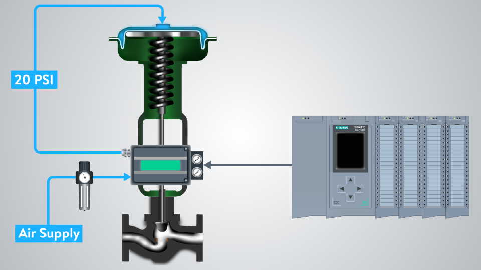
Let’s start with a simple pneumatic circuitry.

The main power of this pneumatic system is coming from the compressed air that is supplied by a compressor.

Directional Control Valve Application Example

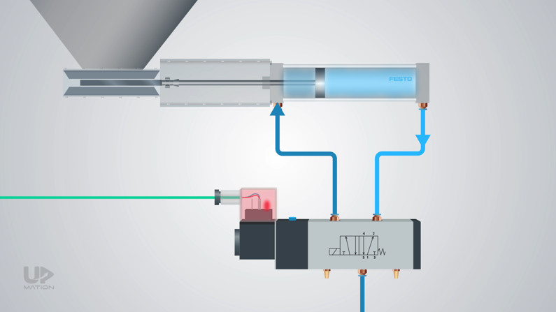
The directional control valve is directing the flow of the compressed air in two different directions to open and close this slide gate valve using its actuator which is a double-acting cylinder.

Flow Direction in Directional Control Valves

A double-acting cylinder has an air chamber on each side to move the piston back and forth.

Pneumatic Double Acting Cylinder

One of the directions expands the cylinder and closes the slide gate valve to block the material coming out of the silo, and the other direction retracts the cylinder to its first position.

Therefore, the slide gate valve is normally closed valve.

How Pneumatic Directional Control Valve Works

Now, let’s take a look at the components and simplified mechanism of the directional control valves.

Directional Control Valve Components

First, is the body or housing of the control valve inside of which, there are the paths that air flows through them.

Housing of a Directional Control Valve

There are some machined holes in the body of the valve that is called Ports.

Ports of the Directional Control Valve

Within the housing, there’s a moving part that leads the air toward different ports of the valve and blocks the others. This moving part is commonly referred to as Spool.

The component that causes the spool to move within the housing, is an electric Solenoid.

Directional Control Valve Components

How Directional Control Valve Works (5/2 Solenoid Valve)

When the spool of the DCV is on its neutral or rest position and the solenoid gets energized by a command from the PLC card, the coil will push the spool and thus it will squeeze the spring on the other side.

As a result, the piston of the cylinder retracts and moves to the right side.

Directional Control Valve Working Principle

As long as the PLC’s command remains on the solenoid, the position of the spool will remain still and the compressed air will cause the piston to keep its last position.

As soon as the PLC removes the command, the spring will return the spool to its first position and the air path will be changed.

Therefore, the air behind the piston will be purged into the atmosphere via the valve exhaust port.

How Pneumatic Control Valve Works

Now, it’s time to learn how to name the directional control valves and how to read their graphic symbols.

Why do They Call it a 5/2 Directional Control Valve?

The valve in our example is known as a 5 by 2 solenoid valve or a 5 by 2 directional control valve.

5 2 Directional Control Valve

But why do we call it 5 by 2?

– The first digit is for the number of ports the valve has.

– The second digit is for the number of states the spool can be in.

Creating a New SIM Table in TIA Portal V15

How to Read a Directional Control Valve Symbol

Reading and interpreting the directional control valve symbols may seem a little bit challenging sometimes.

For instance, let’s consider a 5/2 pneumatic directional control valve symbol.

5 by 2 Directional Control Valve Symbol

Each square in the symbol represents a position or state.

Directional Control Valve Schematic

In each state, some arrows show the paths that air can flow through them on that specific position.

How to Read a Directional Control Valve Symbol

We learned that a 5 by 2 DCV, has 5 ports and this is the ISO designation of the ports which is a more common practice.

ISO Symbol of Directional Control Valves

But sometimes you may see an alternative designation of the Directional Control Valves by alphabets in which;

– The P is for “power” or “pressure” that comes from the air source.

– The Ea and Eb are for the exhaust ports.

– The A and B are the output ports to/from the actuator.

5/2 Directional Control Valve Schematic

There are the signs for electric Solenoid and Spring Return in the Directional Control Valve schematic.

Pneumatic Directional Control Valve Symbol

In our circuit, when the valve is in its rest position, the square besides the spring symbol is active.

Directional Control Valve Symbol

When the solenoid gets energized and the spool changes position, the other square is active.

Generally, the square just beside the solenoid sign is active when the solenoid is energized and this is a rule of thumb for any directional control valve schematic.

Pneumatic Directional Control Valve Schematic

In the end, keep in mind that there are a variety of other directional control valves with more complex functions in different applications that we can check them in future articles.

Thanks for reading another article. Please spread the word by sharing this article:

Our YouTube Channel

Contact Us

Have a question or suggestion?

[email protected]

Youtube channel

What is a Control Valve and How does it Work?

What is a Control Valve and How does it Work?

What is a Control Valve and How does it Work?

Let’s learn about one of the important final control elements in the industry, that is control valve.


A control valve is a type of valve that we use to control the flow, pressure, level or even the direction of the fluid according to the need of the process. Control valves have lots of different types such as glob valves, butterfly valves, diaphragm valves, and so on.

Control Valve Applications

We would almost always like to have control over different parameters of the process like temperature, pressure, level, and so on. To achieve this, obviously, we need a controller like Programmable Logic Controller or PLC for short.

We also need some sensors and transmitters to send data over to PLC or DCS. Finally, we need a piece of equipment to carry out the PLC’s commands which usually called as “Final Control Element.”

A Final Control element can be a pump, a heater, a control valve, and so on.

Control Valve as a Final Control Element

But very often by “Control Valves”, we mean the type of valves that are used not only to fully start and fully stop the flow, but also to control or adjust or in other words throttle the flow of the liquid (or fluid).

Flow Control Valve

By throttling the flow, we achieve our final purpose that is, for example, controlling the temperature of a furnace or the level of a liquid inside a tank.

Different Parts of Control Valves (Globe Valves)

Well, this is a “Globe valve”; One of the most common types of control valves. Let’s check out its different parts;

  • Body of the valve that the fluid will pass through it.

  • Bonnet is connected to the body and covers its inner parts.
Body and Bonnet of the Control Valve
  • Plug that controls, Stop or Start the flow by exposing the liquid flowing inside the pipe.

  • The Actuator that transfers the mechanical power to the plug using the “Stem”.
Globe Valve Different Parts
  • The Positioner is another part of the control valve that commands the Actuator.

The main role of the “Positioner” is to be an interface between the PLC and the Actuator to precisely adjust the plug for being open or closed. There are a variety of Actuator and Positioner types that we have checked them all at the end of this article.

Control Valve Positioner

How Control Valve Positioner Works

Let’s start with an example to understand the operation of the control valve’s Positioner and its relation to the PLC and Actuator.

In this example, we aim to control the temperature of a liquid within a tank by regulating the flow of an additive. This additive will generate heat by having a chemical reaction with the liquid already inside the tank.

How Control Valve Positioner Works

Say, the PLC decides to send a 50% open command to the control valve. This command is based on two items;

– First, the PLC logic

– Second, the feedback it has received by the temperature sensor installed on the tank

This command signal often is in the form of a 4-20 mA DC electrical current and is sent from the PLC. The device that receives this signal on the field is the “Positioner” of the control valve.

How PLC Commands to a Control Valve

As we are using a specific type of pneumatic actuator in this example which needs compressed air to become activated, therefore we chose an electro-pneumatic positioner to command it.

Don’t worry about the names! You’ll understand all of them.

Electro-Pneumatic Positioner

In this case, the positioner plays the role of a “translator” and converts the PLC language to the actuator language! It means that the Positioner will convert the 4-20 mA signal to an air pressure signal.

Positioner Converts the 4-20mA Signal to Air Pressure

You may ask how does this conversion happens?

Well, inside of an Electro-Pneumatic Positioner we have a converter unit which is called “I to P Transducer”. In fact, this transducer converts the 4 mA DC current to a 3 PSI air pressure and the 20mA DC current to a 15 PSI air pressure and of course, they are proportional in the middle range.

Let’s name the 3-15 PSI air pressure as the “Pneumatic Signal”.

How Electro-Pneumatic Positioner Works

With a simple calculation, we understand that in order for the PLC to open the valve for 50% of its full range, it should send a 12mA signal to the Positioner.

Then the Positioner will convert it to a 9PSI signal accordingly and will send it directly to the actuator.

Positioner Converts Milliampere to Air Pressure

But sometimes this amount of air pressure is not enough to move the actuator.

Required Air Pressure to Move the Actuator

Therefore we should increase the air pressure so that it will overcome the spring force of the actuator and moves that.

The Air supply input will provide us with a clean, filtered, regulated air with sufficient pressure, thanks to a filter/regulator device.

Filter Regulator for Control Valves

After all, using the Air supply input and a built-in pressure amplifier, the Positioner will be able to convert the 9PSI air pressure signal to sufficient air pressure for moving the actuator to the right amount.

Components of an Electro Pneumatic Positioner

Same as the PLC that requires feedback by the sensor to decide about the command it is going to send, the Positioner also needs to receive feedback to precisely position the valve stem and open the valve to 50%.

This feedback is sent by the “control valve” to the Positioner using a mechanical mechanism.

In this way, the Positioner will decide how much pressure the actuator needs to move the valve stem.

Control Valve Mechanical Feedback to Positioner

Control Valve Positioner Types

In general, Positioners come into three different categories;

1 – The Electro-Pneumatic Positioners or I/P Positioners that we already discussed in the example.

2 – The Pneumatic Positioners, in which their control signal is a pneumatic signal and they do not need any I/P Transducer modules integrated.

3 – The Digital Positioner or Digital Valve Controller. In addition to an “I to P Transducer”, these positioners take advantage of a “Microprocessor” to fill in the place of the mechanical position feedback.

Control Valve Positioner Types

The input signal or setpoint from the PLC will directly send to the Microprocessor.

The valve position feedback which is measured electronically will also enter the Microprocessor.

Comparing these two electronic signals, the microprocessor is able to adjust the valve position quite accurately in comparison with the other types of positioners.

Digital Valve Controller

Using Digital Positioners, we are able to communicate with the valve by different types of protocols such as HART or Fieldbus protocols like Profibus.

HART and Filedbus Protocols Application in Control Valves

By such digital communications, we can calibrate control valves way more easily using Hand-held communicators without tackling time-consuming and sometimes difficult mechanical adjustments.

Besides, we can send some feedback from the control valve to the PLC or DCS via these communication protocols.

Calibrating a Control Valve Using Handheld Communicator

Standalone I to P Transducer Instead of Positioner

The last point is that the standalone I/P transducers can control the valve independently in case that the accuracy is of less importance.

Meaning that they are not integrated into any kind of positioners and therefore there is no feedback in this case.

I to P Transducer

Now that we’ve got introduced to the positioners, let’s get into the Actuators and their different types.

Control Valve Actuator Types

Generally, we can classify the Actuators into 4 different categories;

– Pneumatic

– Hydraulic

– Electric

– Manual

Control Valve Actuator Types

The Pneumatic actuators are the most used kinds of actuators due to their:

– Simple design

– Fairly low price

– Intrinsically safe characteristic

Electric Actuators have an electric motor inside. They had been designed for:

– On/Off control

– Continuous control

– Where there is no access to compressed air (As their primary application)

Summary

In this article, we learned how a Spring-and-Diaphragm actuator along with an Electro-Pneumatic Positioner adjusts the valve in order for the valve to control the flow of the fluid according to the PLC commands.

Control Valve Components

Thank you for reading this article. Hope you have learned something new.

Please spread the word by sharing this article with your friends:

Our YouTube Channel

Contact Us

Have a question or suggestion?

[email protected]

Youtube channel